Theory
11
5.6 Test Instruments
There are three basic kinds of capacitance, tan δ and power factor test instruments in use.
Although the high accuracy Schering Bridge must be balanced manually and the balance observed on a null
indicator, it has been widely sold and used for decades. The capacitance and dissipation factor can be calculated
by reading the position of the balance elements.
The automatically balanced C tan δ measuring instrument performs measurement by the differential transformer
method. The automatic balancing makes operation very easy.
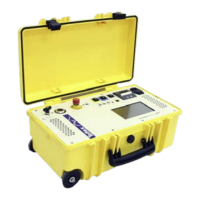
The double vector-meter method is essentially an improvement of the differential transformer method. The MIDAS
micro 2883 incorporates the double vector-meter method.
All three methods are in current use for accurate and repeatable measurements of C tan δ on various test objects.
The differences basically lie in the resolution and accuracy. Different instruments are generally developed
specially for field or laboratory measurement.
Field instruments are specially constructed for rugged field requirements and are equipped with a mobile high
voltage source. In addition, such instruments provide noise suppression for onsite use.
Laboratory instruments have been constructed for indoor use where high accuracy specifications are required.
These test systems are built in a modular construction for higher Test Levels. The systems may be used for daily
routine testing, for high precision long duration tests or for acceptance tests.
5.7 Evaluation of Test Results
5.7.1 Significance of Capacitance and Dissipation Factor
A large percentage of electrical apparatus failures are due to a deteriorated condition of the insulation. Many of
these failures can be anticipated by regular application of simple tests and with timely maintenance indicated by
the tests. An insulation system or apparatus should not be condemned until it has been completely isolated,
cleaned, or serviced. The correct interpretation of capacitance and dissipation factor tests generally requires
knowledge of the apparatus construction and the characteristics of the types of insulation used.
Changes in the normal capacitance of insulation indicate such abnormal conditions as the presence of a moisture
layer, short circuits, or open circuits in the capacitance network. Dissipation factor measurements indicate the
following conditions in the insulation of a wide range of electrical apparatus:
• Chemical deterioration due to time and temperature, including certain eases of acute
deterioration caused by local overheating.
• Contamination by water, carbon deposits, bad oil, dirt and other chemicals.
• Severe leakage through cracks and over surfaces.
• Ionization.
• The interpretation of measurements is usually based on experience, recommendations of the
manufacturer of the equipment being tested, and by observing these differences:
• Between measurements on the same unit after successive intervals of time.
• Between measurements on duplicate units or a similar part of one unit, tested under the same
conditions around the same time, e.g., several identical transformers or one winding of a three phase
transformer tested separately.
• Between measurements made at different test levels on one part of a unit; an increase in slop
(tip-up) of a dissipation factor versus voltage curve at a given voltage is an indication of ionization
commencing at that voltage.