6.3.1 Test Mode „UST” for ungrounded test objects
This test mode is the most common situation when measuring capacitance and dissipation factor. Various
ungrounded capacitances can be measured using this mode, providing that the maximum test current of the
measuring instrument is not exceeded.
When measuring power transformers and HV current transformers, this configuration determines the capacitance
and dissipation factor between the various winding groups.
In this mode the highest measurement accuracy is reached.
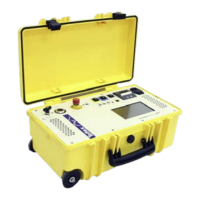
UST A Measurement
The above figure shows a three winding transformer as a typical example (note: for simplicity only one phase per
winding is shown). There exist various capacitances, in between the windings and between the windings and
tank/ground (C
HT
, C
HG
, etc.). Shown is the UST A configuration, where the measuring input A is switched by the
internal relay to the measuring shunt (precision resistor). The inputs B and HV GND are connected to the V (guard)
potential. The current circulates from the High Voltage output through the capacitance C
HL
and the resistor R
x
. All
other capacitances (i.e. C
HT
, C
HG
) are connected to the V-potential. The current flowing through these capacitances
is therefore not taken into the measurement.
6.3.2 Test Mode „GST“ for grounded test objects
This test mode enables the measurement of capacitances that are normally earthed on one side when in
operation. When measuring transformers‚ this configuration measures the capacitance and dissipation factor
between the HV winding and all other windings and the transformer housing.
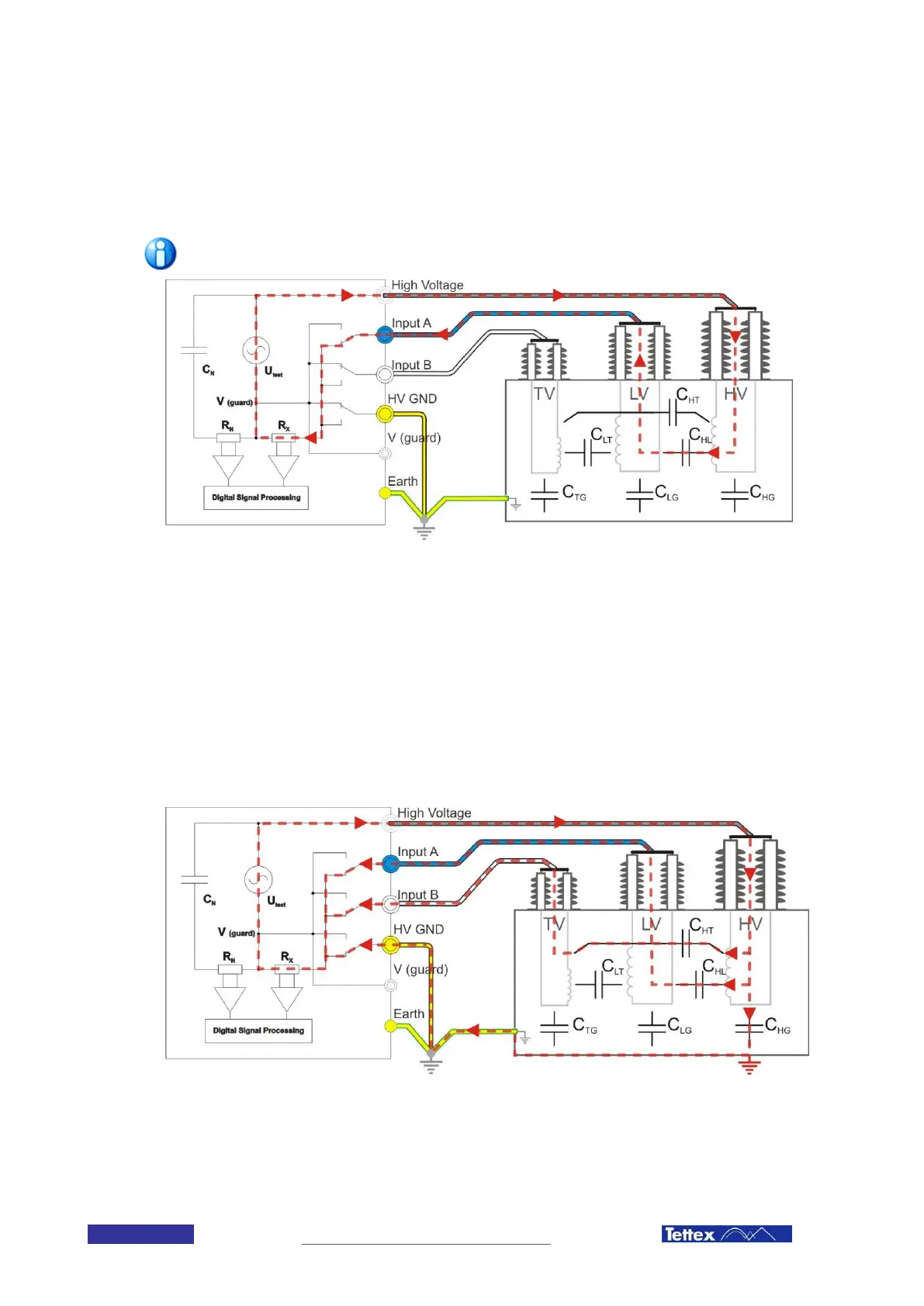
GST A+B measurement
Above figure shows the same three winding transformer in a GST A+B test mode configuration. The current
circulates from the High Voltage output through the capacitances C
HL
, C
HT
and C
HG
and through R
x
. The total
measured capacitance represents the sum of the three capacitances.
 Loading...