Basic Mode
33
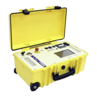
Channel selection
Select which channel(s) should be measured.
The right part indicates how the measurement inputs are
connected internally. Coloured symbols mean the input is
connected to measurement. Greyed out V symbols mean the input
is short-circuited to high voltage ground (guarded).
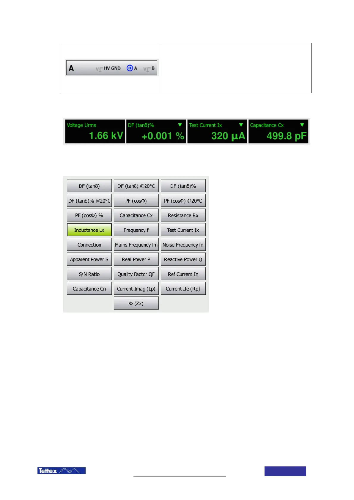
9.1.3 Measurement Bar and Displays
The measurement bar shows the actual measurement displays. The first display is always indicating the voltage on
the high voltage output. The other three displays can be configured by the user. The values can be changed by
clicking on the display. The user is then presented with a selection of measurement values. For further information
about the measurement values see chapter 14 Measurement Values:
If small progress bars appear in the measurement display, this indicates that interference suppression is active.
See chapter 6.4