Operation Elements
25
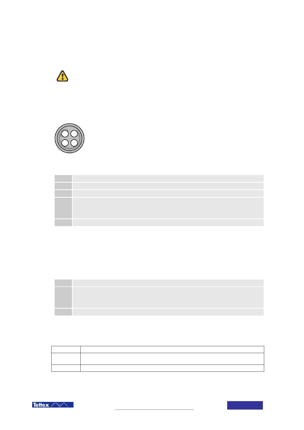
7.1.9 Safety Switch Input
Plug receptacle for connecting the handheld Safety Switch.
The Safety Switch should be used at all times. Never short circuit it and
do not use fixed mechanical locking devices for depressing the switch
button. The switch button must be manually operated at all times.
The safety switch input can also be used as an interlock in an automated system. In this case the responsibility for
the safety lies entirely with the provider of the automated system. Connecting anything different than the equipment
provided by Tettex may result in damaging the device.
(front view)
Pinout
Pin Signal
1 Output +12V protected 45mA
2 Input. Do only connect to Pin 1!
3
+12V Output protected 2.5A max
+12 V when status is “ready”
Intermittent 12 V / 0V when status is “HV on”
0V when not ready (i.e. warning or error present)
4 GND
7.1.10 External Warning Lamp Output
Plug receptacle for connecting the optional external warning lamp (optional, see chapter 15 Accessories and
Options)
Pinout
Pin Signal
1
+12V Output protected 2.5A max:
+12 V when status is “ready”
Intermittent 12 V / 0V when status is “HV on”
0V when not ready (i.e. warning or error present)
2 GND
7.1.11 Warning Lamp
The LED on the front panel indicates the actual high voltage state of the Midas micro 2883 (see chapter 4 Safety).
Off
High voltage output is short circuited no danger from the device.
On
The system is ready to start HV. Selecting HVon on the touchscreen will power up the HV
source.
blinking
HV is on Danger!
1
2 3
4