To keep in mind for the user of the system is that capacitances related to the V-point are bypassed. Make sure
that all unwanted capacitances are related to the V-potential point and their current is flowing directly into the V-
point and not through the measuring shunt R
X.
This has to be evaluated for every measuring setup. The most common ones are described in this manual – for
the other ones the user has to make sure that only the desired capacitances are measured with the chosen test
setup. Most cases can be solved by setting the internal Test Mode Switch matrix correctly which sets unused
measuring cables and connected parts to the V-potential automatically.
The V-potential point is accessible over a 4mm plug on the instruments front panel where the user can connect
external parts of a test setup.
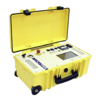
Example: Bypass the leakage current on bushing surface with guarding.
Measurement without guard (V-Potential)
Above figure shows the normal connection in GST gA+B mode to measure the high voltage winding to tank C
HG
.
But with this connection the stray capacitance C
stray
(surface leakage current on bushing surface) is measured in
parallel and therefore causes a minor error on the measurement. The measured value is C
HG
. + C
stray
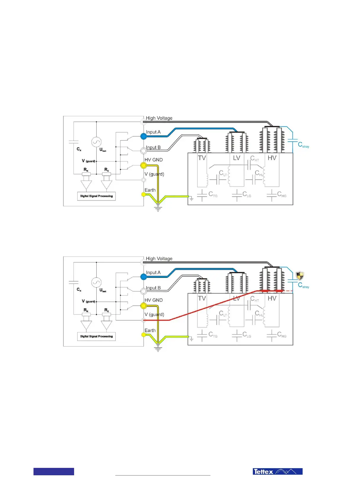
Measurement with connected V-potential point to the powered bushings (guarding)
With guard collars mounted on the bushings surface close to the tank (not touching). These electrodes, connected
to the V-potential point bypass now the leakage current and therefore also the stray capacitance C
stray
The
measured value is now only C
HG
. and the best accuracy is reached.
Note: As guard collar you can use any conducting material as aluminium foil, copper band, etc.
6.3 Test Modes
When measuring transformers and other test objects the problem often arises that, in addition to the „normal“
ungrounded capacitances, capacitances with one side grounded must also be measured (e.g. capacitance
between a winding and an earthed housing).
Conventional measurement systems require the external test setup (cable connections) to be changed for such
 Loading...