Theory
9
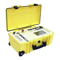
Disc Capacitor
where:
A electrode face
d distance between the electrodes
C capacitance
ε
0
dielectric constant of air (ε
0
=8,8542•10
-12
F/m)
ε
r
relative dielectric constant dependent upon
material
ε ε = ε
0
• ε
r
, dielectric constant
In an ideal capacitor the resistance of the insulation material (dielectric) is infinitely large. That means that, when
an AC voltage is applied, the current leads the voltage by exactly 90°.
After further consideration it must be realized that every insulation material contains single free electrons that show
little loss under DC conditions with P= U
2
/R. Under AC a behaviour called dielectric hysteresis loss occurs which is
analogous to hysteresis loss in iron.
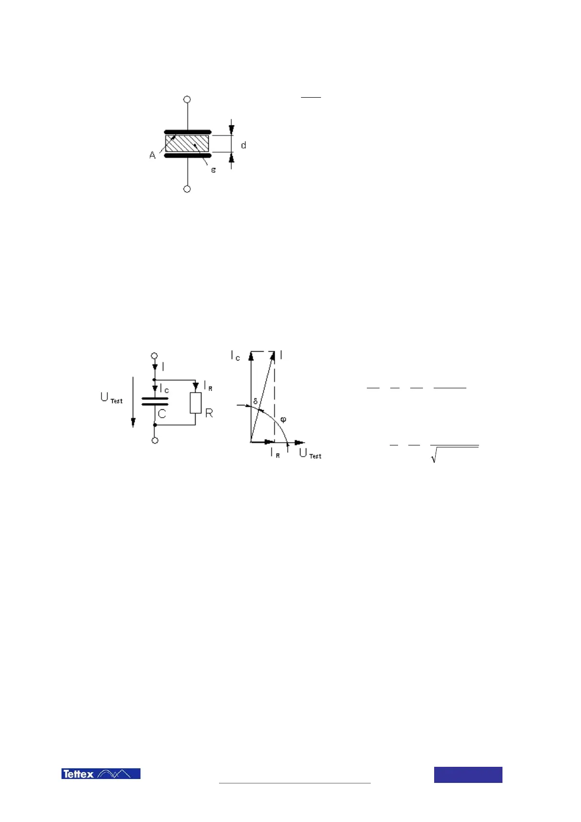
As losses therefore occur in every insulation material, an equivalent diagram of a real capacitance can be
constructed as follows:
Parallel equivalent diagram of a lossy capacitance with vector
diagram
Loss factor (Dissipation Factor)
RCR
X
I
I
Q
P
C
C
R
C
R
⋅⋅
====
ω
δ
1
tan
Power Factor
δ
δ
ϕ
tan
2
1
tan
cos
+
====
C
RR
S
P
I
I
PF
U
Test
applied test voltage
I
C
current through capacitance
I
R
current through resistance (insulating material)
C ideal capacitance
R ideal resistance
Because P = Q • tan δ, the losses which are proportional to tan δ, will usually be given as a value of tan δ to
express the quality of an insulation material. Therefore the angle δ is described as loss angle and tan δ as loss
factor.
 Loading...