Guided Mode
45
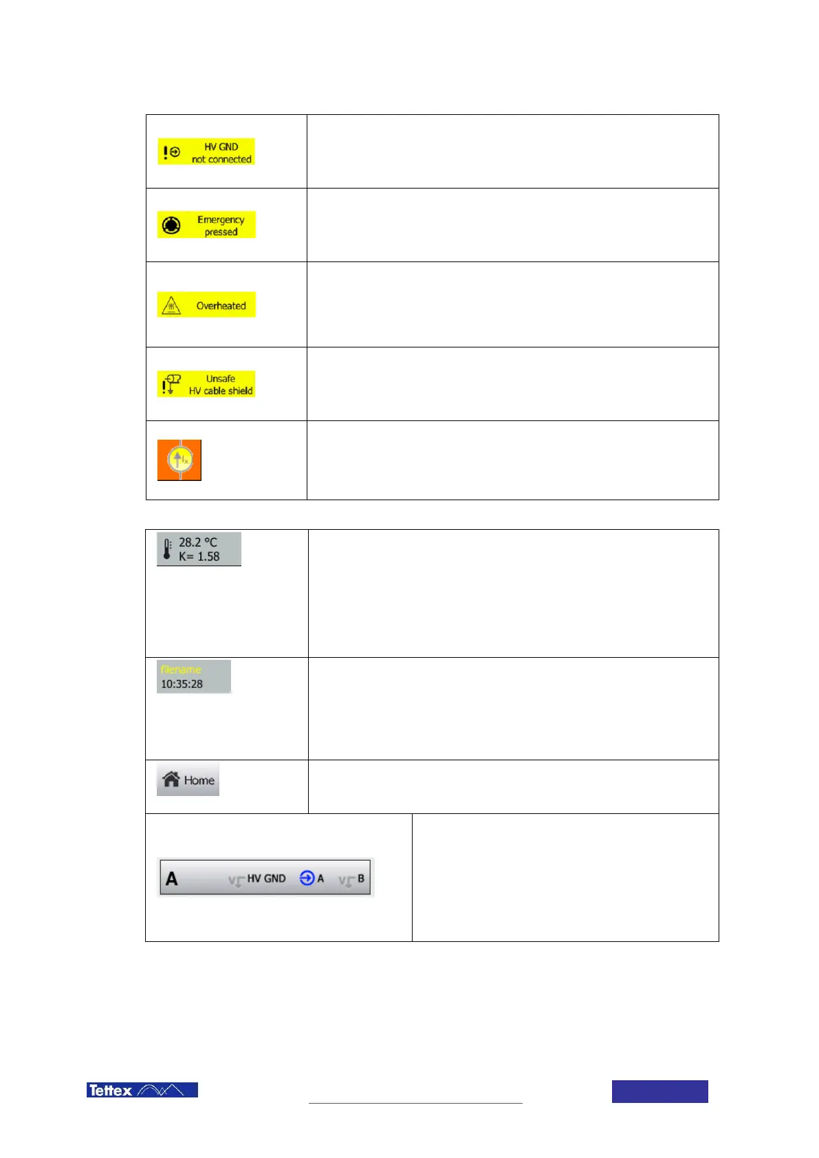
HV GND not connected
The HV GND input is not connected to power ground. This check guarantees
that there is always a low-resistance connection between high voltage ground
and power ground.
Emergency pressed
This warning indicates that the Emergency Stop Button has been pressed and
needs to be released in order to turn on high voltage. Turn the Emergency Stop
Button clock wise to release it.
Overheated
This warning indicates that the internal transformer’s temperature has risen
above the security shutoff temperature. In order to guarantee safety and
integrity, the transformer temperature is monitored and the use of high voltage
is restricted, when the internal transformer gets too hot.
Unsafe HV cable shield
This error indicates that an internal connection of the high voltage ground
cables is broken. Use of the device under these conditions could be harmful
and is therefore prevented.
Excitation Mode active
This symbol shows, that excitation mode is active. In this mode regulation and
stability criteria will be based on the measured current and not on the voltage
and dissipation factor. See also 12.3.1.
Other Elements in the Status Bar
Temperature Correction
The upper line indicates the current temperature of the DUT. This can be a
measured value using the temperature probe or a value entered manually in
the DUT setup.
The second line shows the correction factor considered for the calculation of
the tan δ / DF / PF at 20°C. This factor depends on the temperature and the
type of DUT selected in the setup.
Filename and Time
In the upper line the name of the current file is displayed. If the file has been
changed since the last time it has been saved the filename will be displayed in
yellow.
The second line indicates the current time of day.
Home Button
Leads the user back to the home screen.
Channel selection
Select which channel(s) should be measured.
The right part indicates how the measurement inputs are
connected internally. Coloured symbols mean the input is
connected to measurement. Greyed out V symbols mean
the input is short-circuited to high voltage ground
(guarded).