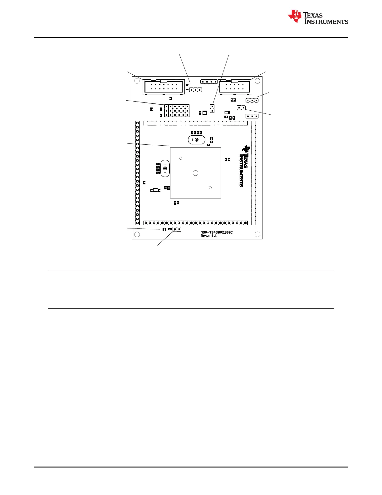
If the system should
be supplied from LDOI (J6),
close JP4 and set JP3 to external
Jumper JP2
Open to disconnect LED
D1
LED connected to P1.0
Orient Pin 1 of MSP430 device
LDOI LDOO/
14
1
2
GND
GND
VCC
1 255 10 1 5 2 0
26 5030 3540 45
5175 55606570
76100 80859095
1 2 3
123
123
123
123
123
123
1 2 3 4
10
1
2
1 2 3
1
JTAG
SBW
Vcc
int
ext
GND
VBAT
DVCC
JTAG
R2
C2
C1
C3
C4
R1
C5
R3
+
C6
+
C7
C8
J5
U1
J1
J2
J3
J4
JP1
JP2
R4
JP5
JP6
JP7
JP8
JP9
JP10
R7
R5
C11
C12
D1
C9
C13
C10
R6
R8
R9
R12
JP3
C17
C18
C19
C14
D3
C16
JP11
Q1
Q2
BOOTST
R10
R11
C15
C20
C21
JP4
D4
J6
Jumpers JP5 to JP10
Close 1-2 to debug in Spy-Bi-Wire mode
Close 2-3 to debug in 4-wire JTAG mode
Jumper JP3
1-2 (int): Power supply from JTAG interface
2-3 (ext): External power supply
Connector JTAG
For JTAG Tool
Connector BOOTST
For Bootloader Tool
Connector J5
External power connector
Jumper JP3 to "ext"
Jumper JP1
Open to measure current
Figure B-75. MSP-TS430PZ100C Target Socket Module, PCB
Note
For bootloader use, the BSL connector and only one of the resistors R10 or R11 must be populated. If
the board is supplied internally, R11 (0 Ω) must be assembled. If the board is supplied externally, R10
(0 Ω) must be assembled, and R11 must be removed.
Hardware
www.ti.com
150 MSP430™ Hardware Tools SLAU278AG – MAY 2009 – REVISED DECEMBER 2020
Submit Document Feedback
Copyright © 2020 Texas Instruments Incorporated

 Loading...


