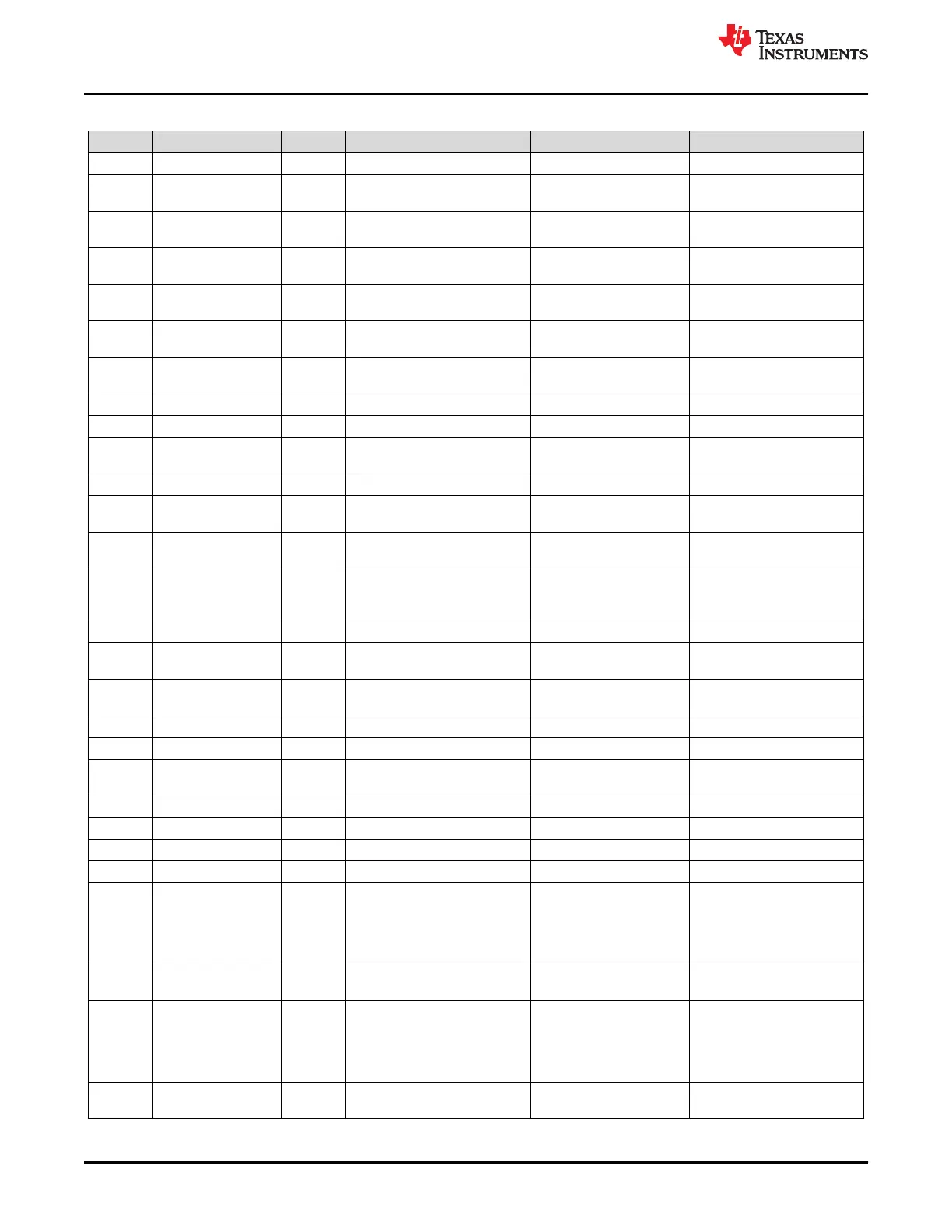
Table B-7. MSP-TS430RHL20 Bill of Materials
Item No. Designator Quantity Description Supplier Part Number Note
1 !PCB 1 Printed Circuit Board
2 BSL 1
Header(Shrouded), 2.54mm,
5x2, Gold, TH
AWHW-10G-0202-T-ND
3 C1 1
CAP, CERM, 1 µF, 10 V, ±10%,
X7R, 0805
490-1695-1-ND
4 C5 1
CAP, CERM, 1100 pF, 50 V,
±5%, C0G/NP0, 0805
490-1623-1-ND
5 C6 1
CAP, CERM, 0.1 µF, 50 V,
±10%, X7R, 0805
490-1666-1-ND
6 C7 1
CAP, CERM, 10 µF, 16 V,
±10%, X5R, 0805
478-5165-1-ND
7 C8, C9 0
CAP, CERM, 22 pF, 50 V, ±5%,
C0G/NP0, 0805
490-3608-1-ND DNP
8 D1 1 LED, Green, SMD 754-1939-1-ND
9 D2 1 LED, Blue, SMD 732-4982-1-ND
10 H5, H6, H7, H8 4
Bumpon, Cylindrical, 0.312 X
0.200, Black
SJ5746-0-ND
11 IC1 1 Socket, QFN-20, 0.5 mm Pitch use IC564-020-130 socket
12
J1, J2, JP5, JP6, JP7,
JP8, JP9, JP10
8 Header, 100mil, 3x1, Gold, TH SAM1029-03-ND
13 J3, J4 2 Header, 100mil, 10x1, Gold, TH SAM1029-10-ND
DNP: Headers are enclosed
in kit. Keep vias free of solder
14 J3, J4 2
Receptacle, 100mil, 10x1, Gold,
TH
SAM1213-12-ND
DNP: Receptacles are
enclosed in kit. Keep vias free
of solder
15 JP1, JP11, JP12 3 Header, 100mil, 2x1, Gold, TH SAM1029-02-ND
16 JTAG 1
Header (shrouded), 100 mil,
7x2, Gold, TH
S9170-ND
17 Q1 1
Crystal, 32.768 KHz, 12.5 pF,
SMD
X1A0001410014
DNP: One Epson Crystal
Included in kit
18 R1 1 RES, 330, 5%, 0.125 W, 0805 541-330ACT-ND
19 R2 1 RES, 200, 5%, 0.125 W, 0805 541-200ACT-ND
20
R3, R10, R19, R20,
R21
5 RES, 0, 5%, 0.125 W, 0805 541-0.0ACT-ND
21 R4, R8, R9 0 RES, 0, 5%, 0.125 W, 0805 541-0.0ACT-ND DNP
22 R7 1 RES, 47 k, 5%, 0.125 W, 0805 541-47KACT-ND
23 R13 0 RES, 47 k, 5%, 0.125 W, 0805 541-47KACT-ND DNP
24 R16, R17 2 RES, 4.7 k, 5%, 0.125 W, 0805 541-4.7KACT-ND
25
SH‑J1, SH‑JP1,
SH‑JP5, SH‑JP6,
SH‑JP7, SH‑JP8,
SH‑JP9, SH‑JP10,
SH‑JP11, SH‑JP12
10
Shunt, 100mil, Gold plated,
Black
3M9580-ND
J1: 1-2, JP1: 1-2, JP5: 2-3,
JP6: 2-3, JP7: 2-3, JP8: 2-3,
JP9: 2-3, JP10: 2-3, JP11:
1-2, JP12: 1-2
26 SW1, SW2 2
Switch Tactile SPST-NO 0.02A
15V
P8079STB-ND
27 SW3, SW4, SW5 3
Switch, DPST, Slide, Off-On, 1
Pos, 0.15A, 30V, TH
GH7727-ND
Install with arrow on part
matching arrow on PCB. SW3
and SW4 should be in the
OFF position, SW5 should be
in the ON position
28
TP1, TP2, TP3, TP4,
TP5, TP6
0 Test Point, Miniature, Black, TH 36-5001-ND DNP
Hardware
www.ti.com
50 MSP430™ Hardware Tools SLAU278AG – MAY 2009 – REVISED DECEMBER 2020
Submit Document Feedback
Copyright © 2020 Texas Instruments Incorporated

 Loading...


