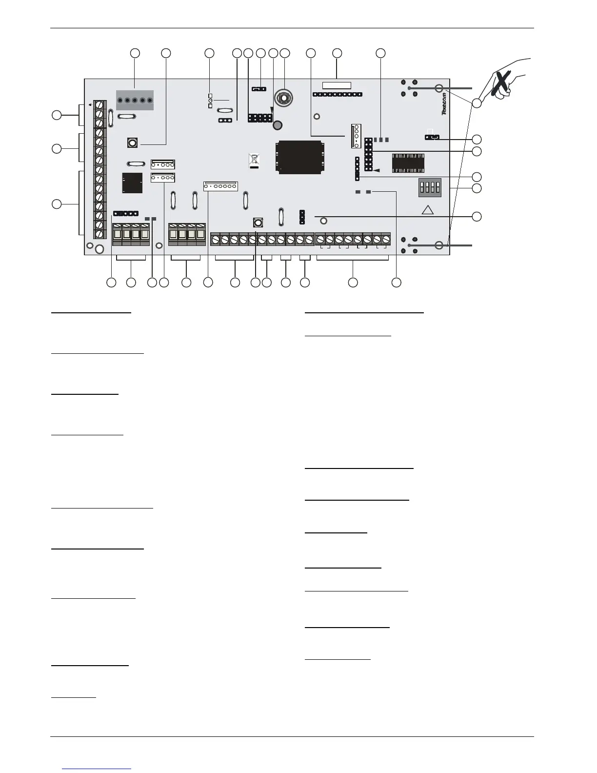
1: Battery Connections
A 12V rechargeable battery must be connected to these terminals in
order to provide continuous system operation in the event of an AC
Mains failure. (protected by 1.6 Amp PTC Fuse)
2: Digicom Power & Inputs
These terminals provide un-fused power; remote reset and line fault
inputs and are normally used for connecting a stand-alone
communicator to the control panel.
3: Digicom Outputs
Outputs 1 to 8 are low current (100mA ‘-ve’ applied) and would
normally be used when connecting a stand-alone communicator to
the control panel. Each output is fully programmable.
4: Engineers Keypad
A portable Engineers keypad can be plugged on here to allow easier
access for programming and testing.
When using a keypad as an Engineers keypad, the address
must be set to ‘10’. The keypad zones and lid tamper
are not monitored.
5: Network Data Connections
Network 1 provides connection for the keypads and zone expanders.
The ‘+’ and ‘–’ terminals provide power whilst the ‘T’ transmits data
and ‘R’ receives data.
6: Network Data Indicators
The red LED indicates that data is flowing out of the control panel
and normally flashes very quickly. The green LED indicates that data
is flowing into the control panel and normally flashes slowly, the
green LED flashes faster as more devices are connected.
7: Communication Ports
Com Port 1 is a serial communications port and can be used for
connecting a PC running Wintex or any supported serial device to the
control panel.
Com Port 2 is a serial communications port and can be used for
connecting a PC running Wintex or any supported serial device to the
control panel.
8: Auxiliary 12V Power
These terminals are for connecting devices that require 12V power
(protected by a 0.9A PTC fuse).
9: Expansion
The Expansion Port can be used for connecting a 60XiD Zone
Expander (see page 32 for details) or an AV Module (see page 40 for
details), X-10 Module or a Memory Module.
10: External Sounder Connections
These terminals are used for connecting to an external sounder unit.
11: Load Defaults Button
Press and hold this button whilst applying power to the control panel
to load the factory default settings. Press and hold this button for 7
seconds with power already on the panel to restore just the Engineer
code to the factory setting of
1234
.
Loading the factory defaults can take up to 30 seconds to
complete.
Loading defaults will only be possible if the NVM has not been
locked.
For a complete list of factory defaults, see the Quick Reference
Guide supplied on the enclosed CD.
12: Auxiliary/Fault Connections
These terminals can be used for monitoring the tamper loop of an
auxiliary device (see page 33 for details).
13: Loudspeaker Connections
These terminals can be used for connecting up to one 8Ω or two
16Ω loudspeakers.
14: Panel Outputs
Outputs 1 & 2 are 500mA ‘-ve’. These outputs are all fully
programmable. (24-W only output 1)
15: Zone Connections
4 Fully programmable zone inputs
16: Ricochet™ Network LED’s
Green LED = Data received by the expander from the panel Red LED
= Data transmitted by the expander to the panel. (The flash rate
depends on the mode and RF activity)
17: Enable 2 wire smoke
Panel Output 1 can be used for connecting up to 10, 12V 2-Wire
smoke detectors.
18: Options Switch
Use to select the receiver functionality.
Switch 1 OFF =not used on 48-W.
Switch 2 OFF = 24-W & 48-W RICOCHET™Mode
ON = Not Used
Switch 3 ON = Impaq Contact-W Wired Input 2 will report as Tamper
(default)
OFF = input 2 will report as an Alarm.
Switch 4 OFF Walk test

 Loading...


