Installation Premier Elite 24,24-W, 48,48-W, 88, 168 & 640 Installation Manual
26 INS176-9
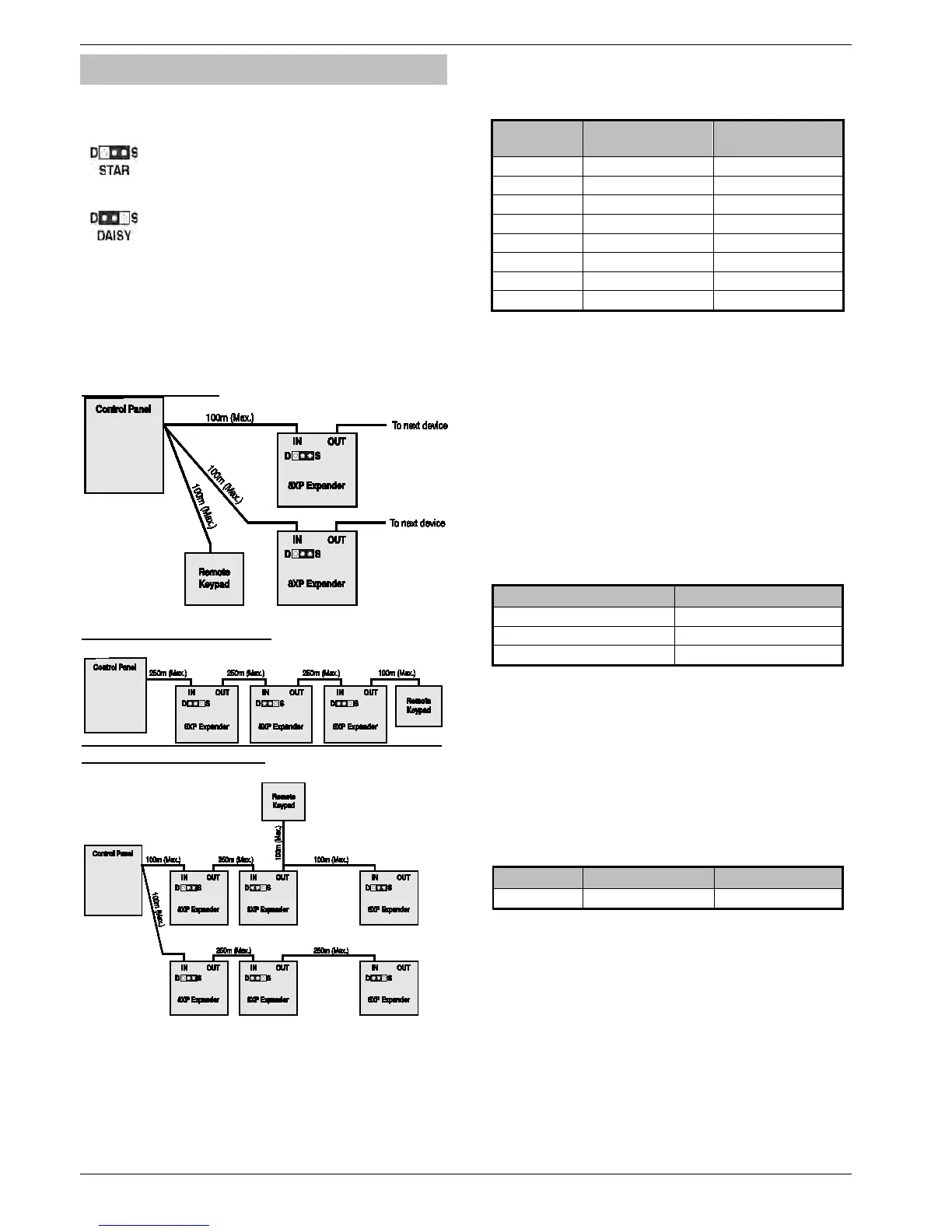
Star and Daisy Jumper Option
The PCB has a jumper JP3 which allows you to select either STAR
(S) or DAISY (D) wiring configuration. The jumper should be set as
follows:
If the network IN connection is wired in parallel with any other
device the jumper MUST be set to the S position. All previous
versions of the expander operated in this mode and for
backward compatibility the unit is supplied with the jumper in
this position.
If the network IN connection is only wired to one device the
jumper should be set to the D position.
When the jumper is set to the STAR position the network data signals
are not boosted between expander and the previous device. In this
mode the network cabling MUST not exceed 100m between devices.
When the jumper is set to the DAISY position the network data
signals are boosted between the expander and the previous device.
This mode will allow expanders on the network to be connected up to
250m apart and MUST only be selected if the expander has one
device connected to the network “IN” connections.
Star wiring example
Daisy chain wiring example
Combined Wiring example
Zone Numbering (24/48/88/168)
The table below shows the zone allocation when the expanders are
installed:
Address
Zones
(Network 1)
Zones
(Network 2)
1* 9 - 16 73 - 80
2* 17 - 24 81 - 88
3** 25 - 32 89 - 96
4** 33 - 40 97 - 104
5*** 41 - 48 105 - 112
6*** 49 - 56 113 - 120
7*** 57 - 64 121 - 128
8*** 65 - 72 129 - 136
Network 2 can only be used on the 168.
For 640 see page 30
* 24/48/88/168/640
** 48/88/168/640 only
*** 88 168 & 640 only
Expander Auxiliary Input
The expander has one programmable input. This auxiliary input can be
used to monitor auxiliary devices such as tamper loops etc. Wire as per
Aux Tamper shown on page 32 (see page 75 for details). The system
will respond as follows:
Input Status System Response
0V Applied Input Secure
0V Removed Input Active
EOL Various *
For further details on how the input status affects the system
please refer to page 75.
* For wiring details, see page 35.
Expander Outputs
The zone expander has eight programmable outputs, which can be
used to drive auxiliary devices such as LED’s, sounders or relays etc.
Wire as per Panel Outputs shown on page 34 (see page 76 for
details). The electrical characteristics for the outputs are shown
below:
Outputs Max Current Type
1 to 8 100mA Switched -ve
Expander Speaker Output
The expander has an output that can be used for driving up to one 16Ω
or two 8Ω loudspeakers (see page 33 for details).
Expander Com Port
The Com Port can be used to connect a PSU200 or amonitored
power supply.
Expander Lid Tamper
The lid tamper of each expander can be disabled if required by fitting
a jumper link across the centre and right hand pins of the ‘Enable
Tamper’ pins (JP2) leaving the left hand pin free. These pins are
located to the left of the address DIL switch just beneath the fuse.

 Loading...


