Premier Elite 24,24-W, 48,48-W, 88, 168 & 640 Installation Manual Installation
INS176-9 27
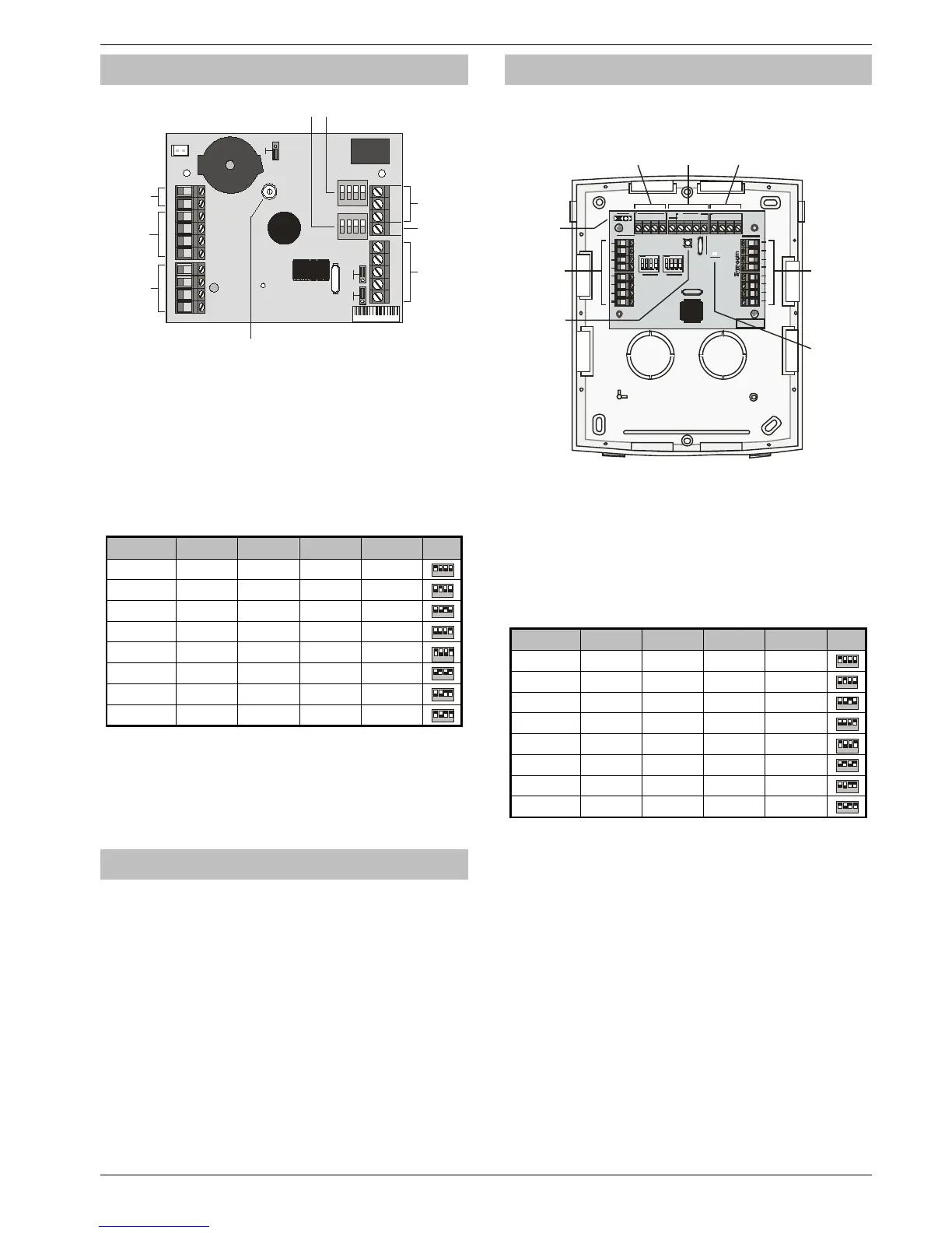
iProx Module
iProx Layout
P IP01 23456
Options
1
ON
2
3
4
1
ON
2
3
4
Address
RTE
N/C N/O
Com
+
T R
Spk +
D0
D1
C1
L1-
C2
L2- L+
Tamper
Ext Coil
Remote LED’s
Relay 1
Ext Int Ext Int
Internal Sounder
Off
On
Door S trike
R el ay
R e q ue st to
E xit I np ut
R emo te
P rox C o il
C onn ec tio ns
S pe a ker
Volume Adj
N e tw o rk
Terminals
W ieg and
I nt e rfa c e
C onn ec tio ns
S pe a ker
Terminals
O pt io n & Ad dr e s s S w itc hes
Connection
The iProx Module is connected to the network terminals located at
the bottom of the control panel (see pages 20 & 21 for details).
Addressing
The iProx Module is addressed as a keypad and will occupy a
keypad slot on the network. The unit must have a unique address,
which must not conflict with keypad or any other iProx Module on
the same network
The following table shows the addressing:
Address DIL 1 DIL 2 DIL 3 DIL 4
1 On or off Off Off Off
Never set two modules on the same network to the same
address.
*88/168 & 640 only
Refer to the iProx Module manual for programming and operating
instructions.
60iXD Zone Expander
The 60iXD expander provides the following facilities:
• Two iD loops each supporting up to 30 biscuits
• Fused 12V output for powering detectors
• Engineer’s keypad port for local iD diagnostics
OP16 Output Expander
Output Module Layout
Po wer L E D
Ta m p e r
S witc h
Ne twor k
Te rmi n a ls
Aux 12V
and Tamper
Ou tput
+
-
T R
+
-
T R
+
B an k 2
O utputs
1 to 8
B an k 1
O utputs
1 to 8
-
++
-
Ne twor k
Te rmi n a ls
Eng ineer s
Key pad
Inte rfa c e
+
-
T R
+
-
T R
+
-
++
-
BAR C ODE
Connecting Output Modules
Output modules are connected to the network terminals located at
the bottom left hand corner of the control panel (see pages 20 & 21
for details).
Output Module Addressing
Each output module must be assigned a different address using the
DIL switches located in the centre of the PCB.
The table below shows the expander addressing:
Address DIL 1 DIL 2 DIL 3 DIL 4
1 On or off Off Off Off
* 88 and 168 only
** 168 only
In order for an output module to mimic zone expander outputs,
the output module must be addressed the same as the zone
expander that it is mimicking.
Any combination of addresses can be used on each output
module i.e. Bank 1 can be addressed to mimic expander 3
and Bank 2 can be addressed to mimic expander 8.
Bank 1 switch sets the address of the device that Bank 1
outputs 1 to 8 will mimic.
Bank 2 switch sets the address of the device that Bank 2
outputs 1 to 8 will mimic.

 Loading...


