Installation Premier Elite 24,24-W, 48,48-W, 88, 168 & 640 Installation Manual
28 INS176-9
Output Module Numbering
The table below shows the output allocation when the output
modules are installed,
Address
Outputs
(Network 1)
Outputs
(Network 2) **
1 Expander 1, 1 - 8 Expander 1, 1 - 8
2 Expander 2, 1 - 8 Expander 2, 1 - 8
3 * Expander 3, 1 - 8 Expander 3, 1 - 8
4 * Expander 4, 1 - 8 Expander 4, 1 - 8
5 ** Expander 5, 1 - 8 Expander 5, 1 - 8
6 ** Expander 6, 1 - 8 Expander 6, 1 - 8
7 ** Expander 7, 1 - 8 Expander 7, 1 - 8
8 ** Expander 8, 1 - 8 Expander 8, 1 - 8
Network 2 can only be used on the 168
* 88 and 168 only
** 168 only
for 640 see page 30
Outputs
The output module has 16 programmable outputs, which can be
used to drive auxiliary devices such as LED’s, sounders or relays etc.
Wire as per Panel Outputs shown on page 34 (see page 76 for
details). The electrical characteristics for the outputs are shown below:
Bank Outputs Max Current Type
1 1 to 8 100mA Switched -ve
2 1 to 8 100mA Switched -ve
Tamper Output
The tamper switch on the output module is connected to the tamper
output at the top of the module. If monitoring of the lid tamper is
required, this output must be connected to a suitable input on the
control panel or zone expander.
RM8 Relay Module
The Premier Elite RM8 Relay Module is compatible with any control
panels that have a plug on RedCARE/Dualcom footprint.
Features
•
8 relay outputs (12V, 3Amp each)
• 8 Auxiliary inputs (-ve applied)
• Auxiliary 12V output (protected by a 1 Amp fuse)
• Relay ON indication via LED’s
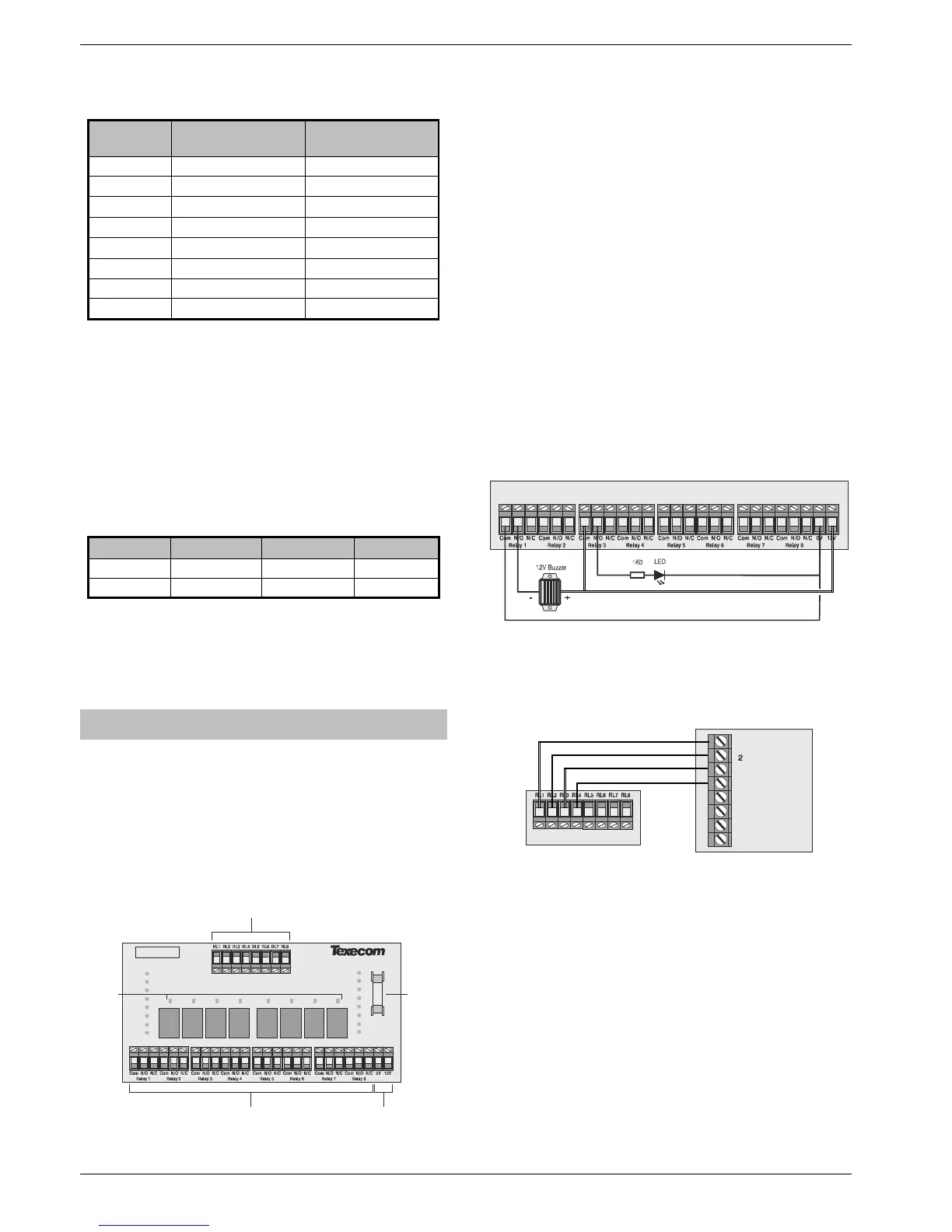
PCB Layout
Installation
Before attempting to install the RM8 Relay Module, isolate ALL power
from the control panel (AC Mains and Battery). Do not continue if
there is power still present on the control panel.
Plugging on the Relay Module with power still present on
the control panel may damage the Relay Module, control
panel or both and invalidate any warranty.
Plugging on the Relay Module
1. Ensure that the Relay Module is the correct way up (see
page Error! Bookmark not defined.).
2. Gently press down on the Relay Module until the relay
Module is seated correctly.
3. Reconnect power to the control panel.
Testing on the Relay Module
1. For plug on operation, test the Relay Module in accordance
with the control panel instructions.
2. To test the auxiliary inputs, apply 0V to each input in turn
and ensure that the correct LED illuminates and a click is
heard from the relay.
Connecting Outputs
The RM8 Relay Module has 8 outputs. These outputs can be used to
drive auxiliary devices such as LED’s, sounders or communicators etc.
Each output is a clean contact relay rated at 3A @ 12V. The diagram
below shows typical wiring examples for the outputs:
Connecting Inputs
The RM8 Relay Module has 8 auxiliary inputs. These inputs can be
used to activate the relays from an external source. Each input is -Ve
applied and draws up to 30mA.
The diagram below shows typical
wiring examples for the inputs:

 Loading...


