Installation Premier Elite 24,24-W, 48,48-W, 88, 168 & 640 Installation Manual
20 INS176-9
Connecting Devices to the Network
Before connecting keypads, zone expanders and output modules,
isolate ALL power from the control panel (AC Mains & Battery). Do
not continue if there is still power present on the control panel.
Connecting devices with power still present on the control
panel may damage the device or control panel and invalidate
any warranty.
Keypads, zone expanders and output modules are all connected to the
same network terminals located at the bottom left hand corner of the
control panel and may be connected serially (daisy chain), in parallel
(star) or any combination of the two (see Figure 1, page 21 for details).
No more than 8 zone expanders, 8 keypads and 4 output modules
can be connected to each network.
The maximum number of devices that can be connected in total
will depend on the control panel fitted.
Whenever new devices are connected to the networks, they must be
confirmed onto the system using the ‘Confirm Devices’ menu option
(see page 117 for details).
Wiring the Network
The networks are made up of four terminals incorporating power and
data. To ensure correct operation, all four terminals on the device
must be connected to the corresponding terminals on the control
panel, or previous device (see Figure 1, page 21 for details). The
table below shows each terminal and its description:
Terminal Description
+ +12V Supply
- 0V Supply
T Transmit Data
R Receive Data
Devices can be connected using 4-core cable. However, it is recommended
that 6 or 8-core cable is used as the spare cores can be used to ‘Double Up’
on the power connections if needed.
Standard 7/0.2 alarm cable can be used for most installations.
However, under certain conditions it may be necessary to use
screened cable.
Cable Distances
The maximum recommended distance for devices when using
standard 7/0.2 alarm cable is:
• 250m for each branch when using the star (parallel)
configuration
• When using a daisy chain (series) configuration the maximum
distance will depend on the number of devices connected on
the chain. The more devices that are connected, the shorter the
distance to the last device (this is due to voltage drop in the
cable)
Whichever method of wiring configuration is used, ensure that the
voltage between the ‘+’ and ‘–’ terminals at each device is no lower
than 10.0V when the system is running on the standby battery.
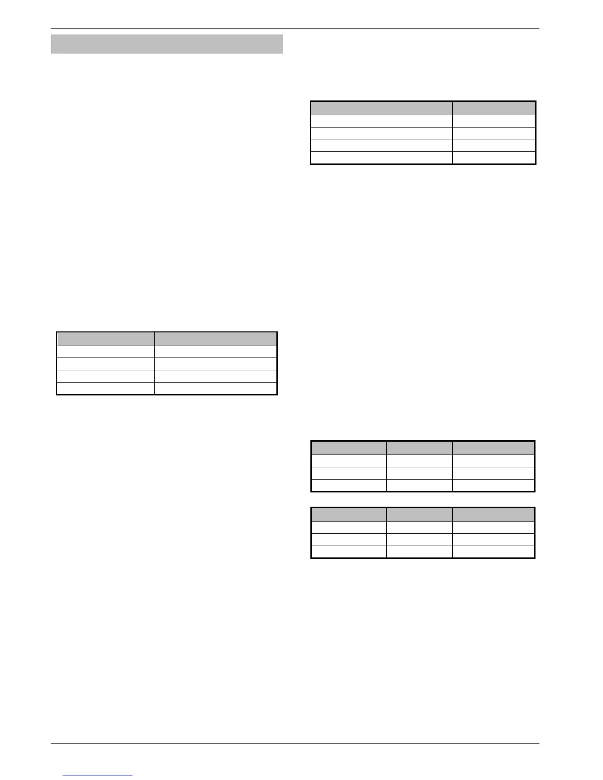
The table below shows maximum cable runs when one keypad or
expander is installed using standard 7/0.2 alarm cable with various
loads:
Configuration Max. Cable Run
1. Keypad + 2 PIR’s @15mA 250m
2. Expander + 2 PIR’s @15mA 250m
3. Expander + 8 PIR’s @15mA 100m
4. As No. 3 + 16Ω Speaker
30m
Distances of up to 1km can be achieved between the control panel and
a device. However, a power supply must be installed close to the
device to power it locally, this will help to overcome voltage drop
caused by the long cable run.
Overcoming Voltage Drop
There are several ways to overcome voltage drop:
• Use thicker lower resistance cable. Standard 7/0.2 alarm cable
has a resistance of 8Ω per 100m
• Double up on the power connections – this will require using a 6
or 8-core cable rather than a 4-core cable
• Install a power supply to power the device locally, remember to
common the two negative connections
Installing a Power Supply
When a power supply is installed, the 0V connections on the power
supply must be connected through to 0V on the control panel and
the +12V connection between the control panel and the device must
be disconnected (see Figure 2, page 21 for details).
Network Diagnostics
Each network has two LED’s to indicate data flow. The red LED
indicates data flowing out of the ‘T’ terminal and the green LED
indicates data flowing into the ‘R’ terminal. The table below shows
each LED status and its meaning:
LED Status ‘T’ Wire OUT ‘T’ Wire IN
Red LED Flashing Normal Normal
Red LED On Panel Fault Cable Short
Red LED Off Panel Fault Panel Fault
LED Status ‘R’ Wire OUT ‘R’ Wire IN
Green LED Flashing Panel Fault Normal
Green LED On Panel Fault Cable Short
Green LED Off Normal No Data From Devices
The LED’s are provided as an aid for fault finding and therefore
should not be completely relied upon to indicate that there is a
fault.

 Loading...


