clamping torque: 17 N·
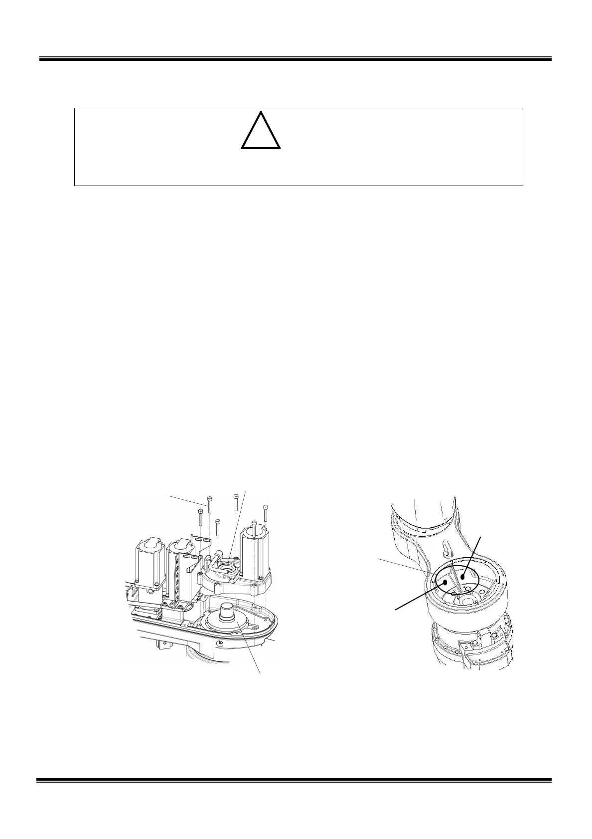
Center gear of axis 2 reduction gear
Connector
connecting position
Power drive
cable air tubing
• Be sure to attach the “O” ring and apply the liquid gasket. Otherwise, grease
will leak from the gear case set surface and motor set surface.
5) Attach the gear case to the arm 2 with six (6) bolts (M6 × 35). Make sure that
the center gear of the axis 2 reduction gear is mounted. Mount the axis 3
tension adjustment bolt (M4 × 35) then. (Adjustment of the axis 3 tension is
unnecessary.)
6) Pass the disconnected cables and air tubes up to the connector connecting
position on the upper side of the arm 1.
As the inner diameter of the center shaft is small, observe the following order
when passing the cables.
Encoder cables (large connectors) → Power drive cables (small connectors) →
Air tubes
Especially, when passing the encoder cable connectors, pass them one by one
so as to arrange them vertically. DO NOT pull them out by force.
In the arm 1, the encoder cables and power drive cables are separated on the
right and left sides. See the figure below.
7) Connect the cables and air tubes thus passed as originally arranged.
8) Mount the cover bracket, and secure it together with the connector panel.
STE 85306
– 39 –
 Loading...


