132 Connectors
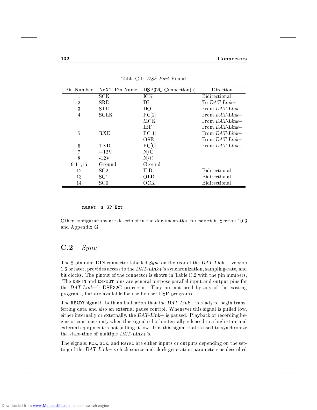
Table C.1:
DSP-Port
Pinout
Pin Number NeXT Pin Name DSP32C Connection(s) Direction
1 SCK ICK Bidirectional
2 SRD DI To
DAT-Link
+
3 STD DO From
DAT-Link
+
4 SCLK PC[2] From
DAT-Link
+
MCK From
DAT-Link
+
IBF From
DAT-Link
+
5 RXD PC[1] From
DAT-Link
+
OSE From
DAT-Link
+
6 TXD PC[0] From
DAT-Link
+
7 +12V N/C
8 -12V N/C
9-11,15 Ground Ground
12 SC2 ILD Bidirectional
13 SC1 OLD Bidirectional
14 SC0 OCK Bidirectional
naset -s GP-Ext
Other congurations are described in the documentation for
naset
in Section 10.3
and Appendix G.
C.2
Sync
The 8-pin mini-DIN connector lab elled
Sync
on the rear of the
DAT-Link
+, version
1.6 or later, provides access to the
DAT-Link
+'s synchronization, sampling-rate, and
bit clocks. The pinout of the connector is shown in Table C.2 with the pin numbers,
The
DSPIN
and
DSPOUT
pins are general purp ose parallel input and output pins for
the
DAT-Link
+'s DSP32C processor. They are not used by any of the existing
programs, but are available for use by user DSP programs.
The
READY
signal is b oth an indication that the
DAT-Link
+ is ready to begin trans-
ferring data and also an external pause control. Whenever this signal is pulled low,
either internally or externally, the
DAT-Link
+ is paused. Playback or recording be-
gins or continues only when this signal is b oth internally released to a high state and
external equipment is not pulling it low. It is this signal that is used to synchronize
the start-time of multiple
DAT-Link
+'s.
The signals,
MCK
,
SCK
, and
FSYNC
are either inputs or outputs dep ending on the set-
ting of the
DAT-Link
+'s clock source and clo ck generation parameters as describ ed