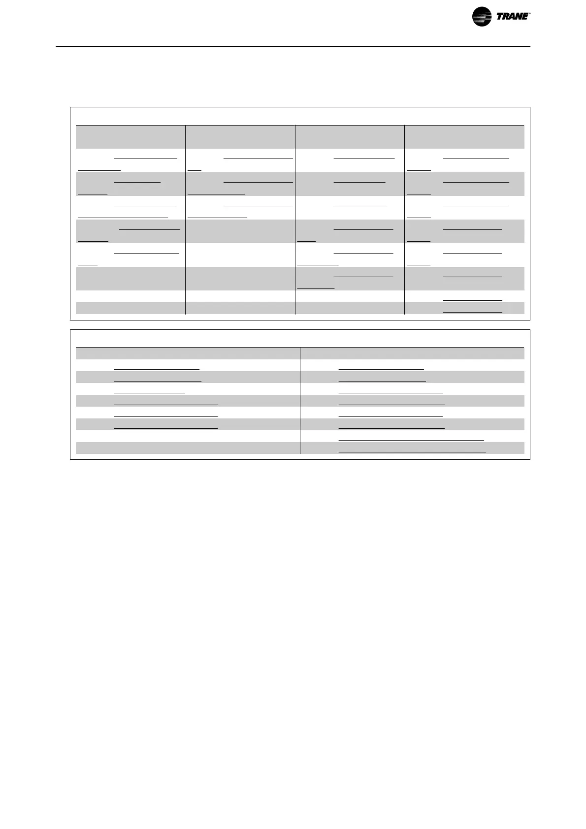
Function Set-ups parameters
The Function Setups parameters are grouped in the following way:
Q3-1 General Settings
Q3-10 Adv. Motor Set-
tings
Q3-11 Analog Output Q3-12 Clock Settings Q3-13 Display Settings
par.1-90 Motor Thermal
Protection
par.6-50 Terminal 42 Out-
put
par.0-70 Date and Time par.0-20 Display Line 1.1
Small
par.1-93 Thermistor
Source
par.6-51 Terminal 42 Out-
put Min Scale
par.0-71 Date Format Par.0-21 Display Line 1.2
Small
par.1-29 Automatic Mo-
tor Adaptation (AMA)
par.6-52 Terminal 42 Out-
put Max Scale
par.0-72 Time Format Par.0-22 Display Line 1.3
Small
par.14-01 Switching Fre-
quency
par.0-74 DST/Summer-
time
Par.0-23 Display Line 2
Large
par.4-53 Warning Speed
High
par.0-76 DST/Summer-
time Start
Par.0-24 Display Line 3
Large
par.0-77 DST/Summer-
time End
par.0-37 Display Text 1
par.0-38 Display Text 2
par.0-39 Display Text 3
Q3-2 Open Loop Settings
Q3-20 Digital Reference Q3-21 Analog Reference
par.3-02 Minimum Reference par.3-02 Minimum Reference
par.3-03 Maximum Reference par.3-03 Maximum Reference
par.3-10 Preset Reference par.6-10 Terminal 53 Low Voltage
par.5-13 Terminal 29 Digital Input par.6-11 Terminal 53 High Voltage
par.5-14 Terminal 32 Digital Input par.6-12 Terminal 53 Low Current
Par.5-15 Terminal 33 Digital Input par.6-13 Terminal 53 High Current
par.6-14 Terminal 53 Low Ref./Feedb. Value
par.6-15 Terminal 53 High Ref./Feedb. Value
How to Program
TR200 Programming Guide 31

 Loading...


