b. Dismount the diff-case (RH) and the snap ring
(LH) by installing push bolt as shown in Fig.5-55
c. The number of installed shims should be
written down or memorized for later reference.
d. Remove ring gear as a set.
e. When disassembling the ring gear set further,
remove bearing with a puller.
f. Remove the bolts, and the ring gear can then be
separated from dif-cases
g. Pull out the diff pinion shaft and take out the
dif-pinions and dif-side gears.
h. Remove the pinion metal tightening bolts and
take put drive pinion and related parts as an
assembly.
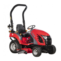
i. Release the lock of nut and remove the nut
j. Push out drive pinion from drive pinion metal
on a press.
k. Remove the bearing from the drive pinion with
a special tool.
5-31
Fig.5-57
Fig.5-58
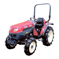
Fig. 5-56
14 2
3
5
1.Bolts(M10) 2.Shim(0.1t) 3.Diff. Metal
4.Bolts 5.Shim(0.2t)
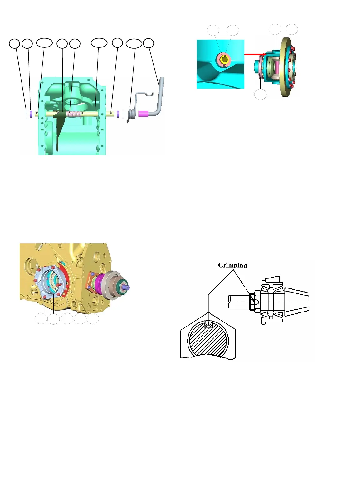
a. Remove the the diff-lock parts.
Fig. 5-55
1.Diff-lock shaft 2.Diff-lock metal
3.Pressure spring 4.collar 5.10. Spring pin
8.Oil seal 9.Diff-lock pedal 11. Spring
5
1 2
34
1.Diff-pinion pin 2.Bolts
3,4.Spring pin 5.Diff-lock clutch
Note : When assemble the spring pin,
Be sure the spring pin should be different
direction (Ø5 and Ø8)
1
3
5
8
9
10
2
11
4