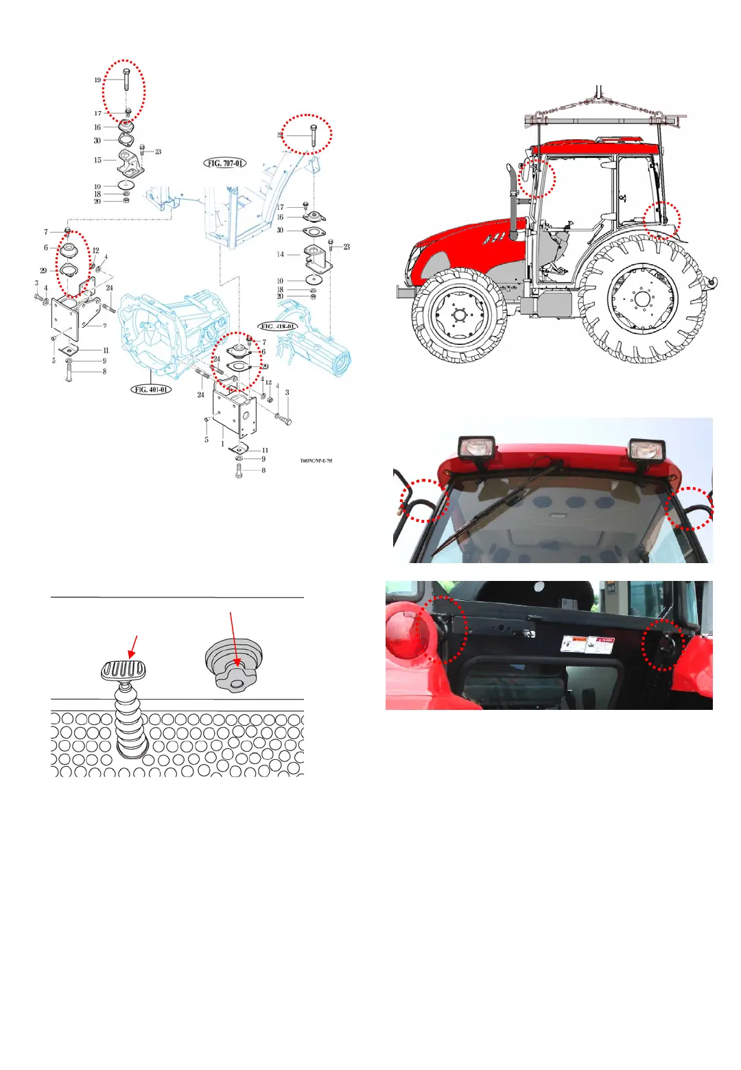
Fig.2-42 Rubber mounting
16) Lift the cabin gradually taking care not to
allow the shaft of the slow-return check valve
and its hole in the floor to interfere with each
other.
Fig.2-43 Slow return shaft
15) Remove four rubber mounts.
2-14
Note : Lift up the cabin gradually making sure
that all relevant wiring. Piping, cock and
links are disconnected.
17) Remove the Cabin assembly.
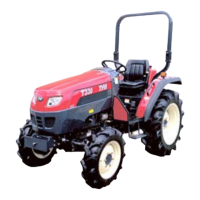
Fig. 2-45 : 4 hangers to be lifted
2 x Bolts
Front LH, RH
2 x Bolts
Rear LH, RH
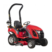
Fig. 2-44
Dif-Lock Pedal
Slow return check
Valve Knob