Pg. 29 di 80
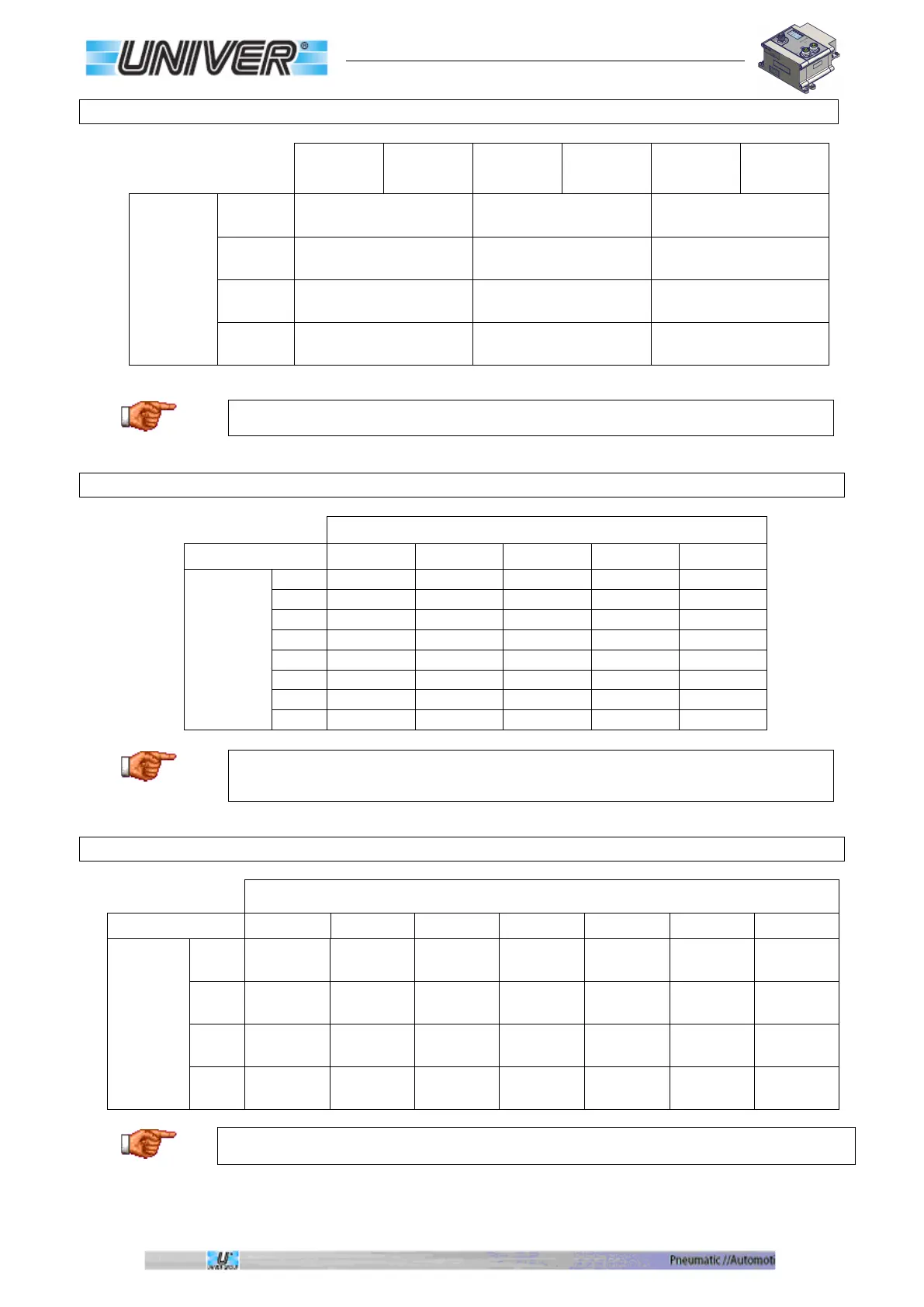
Allocation of manifold valve Byte/Bit
Coil
Consume
Byte-Bit
Coil
Consume
Byte-Bit
Coil
Consume
Byte-Bit
Valve
function
Side 14 1 0-0 9 1-0 17 2-0
Side 12 2 0-1 10 1-1 18 2-1
Side 14 3 0-2 11 1-2 19 2-2
Side 12 4 0-3 12 1-3 20 2-3
Side 14 5 0-4 13 1-4 21 2-4
Side 12 6 0-5 14 1-5 22 2-5
Side 14 7 0-6 15 1-6 23 2-6
Side 12 8 0-7 16 1-7 24 2-7
TC modules always use 24 Bit (3 Bytes) regardless the actual number of valves.
Allocation of Byte/Bit of further output modules
Slot
1 2 3 4 5
Pin-port
P 1-4
3-0 4-0 5-0 6-0 7-0
P 1-2
3-1 4-1 5-1 6-1 7-1
P 2-4
3-2 4-2 5-2 6-2 7-2
P 2-2
3-3 4-3 5-3 6-3 7-3
P 3-4
3-4 4-4 5-4 6-4 7-4
P 3-2
3-5 4-5 5-5 6-5 7-5
P 4-4
3-6 4-6 5-6 6-6 7-6
P 4-2
3-7 4-7 5-7 6-7 7-7
The maximal number of configurable digital outputs is 64/88 Bit (8/11 Bytes), based on
the models of the used connectors.
Allocation of Byte/Bit of further input modules
Byte-Bit Produces
Slot
1 2 3 4 5 6 7
Pin-ports
P 1-4
0-0 1-0 2-0
3-0 4-0 5-0 6-0
P 1-2
0-1 1-1 2-1
3-1 4-1 5-1 6-1
P 2-4
0-2 1-2 2-2
3-2 4-2 5-2 6-2
2-2
0-3 1-3 2-3
3-3 4-3 5-3 6-3
3-4
0-4 1-4 2-4
3-4 4-4 5-4 6-4
P 3-2
0-5 1-5 2-5
3-5 4-5 5-5 6-5
P 4-4
0-6 1-6 2-6
3-6 4-6 5-6 6-6
P 4-2
0-7 1-7 2-7
3-7 4-7 5-7 6-7
The maximal number of configurable digital inputs is 64 Bit (8 Byte).
 Loading...