Pg. 71 di 80
Error codes in the Profibus diagnostics messaging
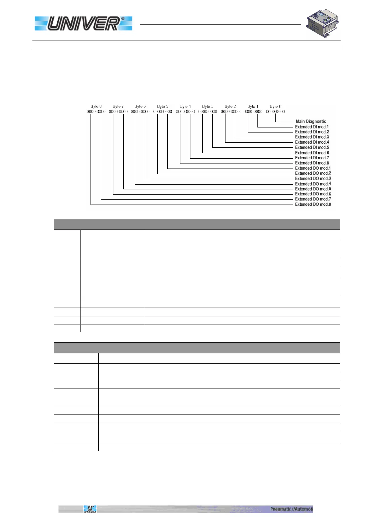
The diagnostics includes 9 bytes which include all the possible errors of the various
installable modules (8 input modules and 8 output modules).
The first byte is the main diagnostics. The next 8 bytes are the extended diagnostics and are
divided into 4 bytes for the input modules and 4 bytes for the output modules. Each byte
contains information of 2 modules, that is the extended diagnostics is divided into Nibbles.
BITS OF THE MAIN DIAGNOSTICS
Bit Name Description
0
24V Main power loss
This bit at 1 indicates the lack of VA24 power supply (pin4 of the power
connector). In this condition the valve coils will not be powered even if the
Module fail
This bit at 1 indicates that the module is faulty (replace the module).
2
Output fail
This bit at 1 indicates that one or more outputs are overloaded or in short circuit,
this applies both to the integrated manifold and to the output modules (1).
3
High noise level
This bit at 1 indicates that a communication error has been detected on the
internal bus, caused by the high level of noise, due to bad wiring, lack of
grounding, or capacitive coupling of the connecting cables.
4
Input power loss
This bit at 1 indicates an overload or a short circuit in one or more connectors of
the input module.
Clamp Error
This bit at 1 indicates that one or more electric clamps are in error.
Reserved
Module info Monitor
This bit at 1 indicated that an extended module diagnostics is available.
NIBBLES OF THE EXTENDED DIAGNOSTICS
Binary Description
This value indicates that no error is present.
This value indicates the lack of power supply (VA24). (2)
This value indicates that one or more outputs are overloaded or in short circuit. (2)
0011
This value indicates that a communication error has been detected on the internal bus, caused by a
high level of noise, due to bad wiring, lack of grounding, or capacitive coupling of the connection
This value indicates a module failure.
This value indicates an overload or short circuit in one or more connectors of the input modules.
This value indicates that one or more electric clamps are in error (output FAULT active).
0111
This value indicates that one or more control outputs for the electric clamps are overloaded or in short
circuit.
Not yet assigned
(1) If the error is generated by the integrated manifold, it is possible to reset the error by turning all the 24 outputs, wait for at least 7
seconds and reactivate the needed outputs again.
In case of short circuit or overload all the 24 outputs will be switched off.
(2) Only on output modules.
 Loading...