Pg. 33 di 80
Supply and separator modules
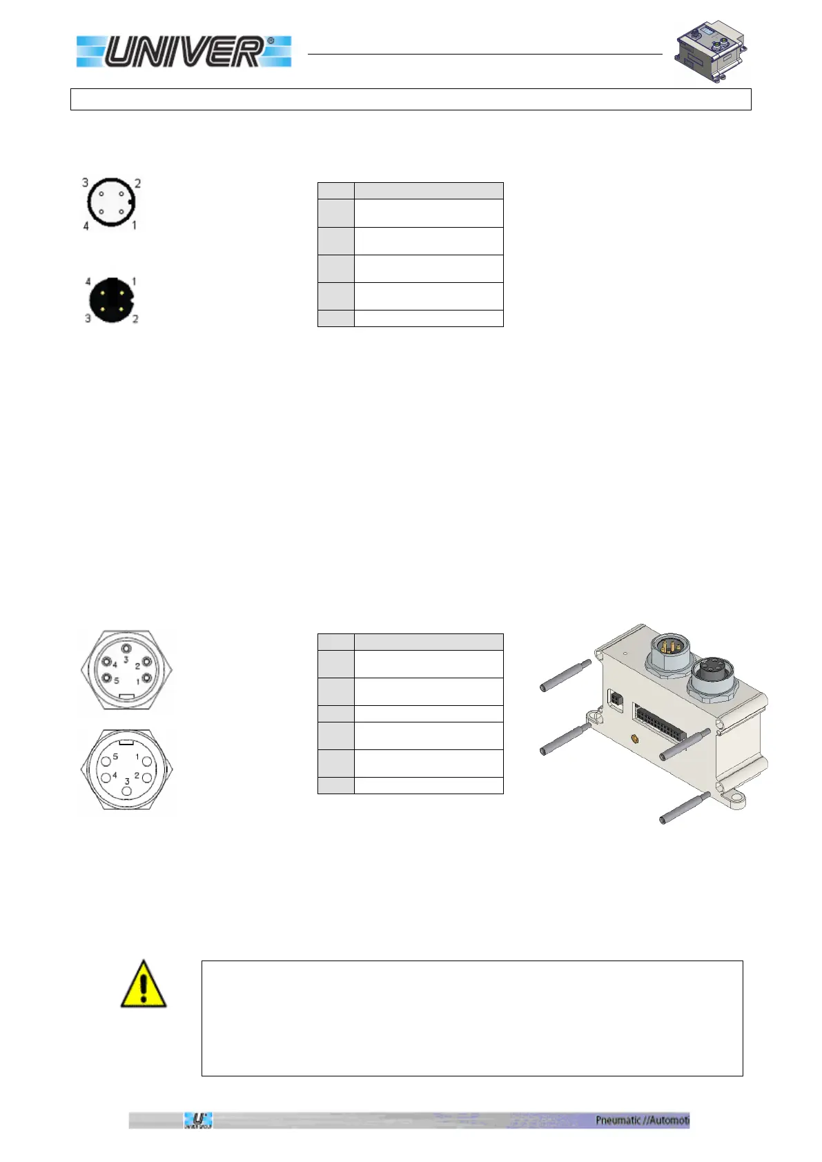
COD.TCXUSM12
Power supply/ M12 Separator
M12 Male A code
Contact side view
M12 Female A code
Contact side view
(Preliminary)
COD.TCXUS78
Power supply/ 7/8 separator
Power Supply IN
7/8 Male 5-pole
Contact side view
Power Supply OUT
7/8 Female 5-pole
Contact side view
When using one of these modules with standard communication systems, keep in mind
that its male power
connector (which has uncovered pins) is energized, being connected in parallel,
therefore, if not used, it
must be protected with a special plug.
To use the module as “Separator” simply remove the JP1 Jumper located on the lower
printed circuit near the 26-pole connector
1
Positive logic and input
power supply (VLS24)
2
Negative output power
supply (0VA)
3
Negative logic and input
power supply (0VLS)
4
Positive output power
supply (VA24)
1
Negative output power
supply (0VA)
2
Negative logic and input
power supply (0VLS)
4
Positive logic and input
power supply (VLS24)
5
Positive output power
supply (VA24)
 Loading...