2.4. Controller I/O
2.4 Controller I/O
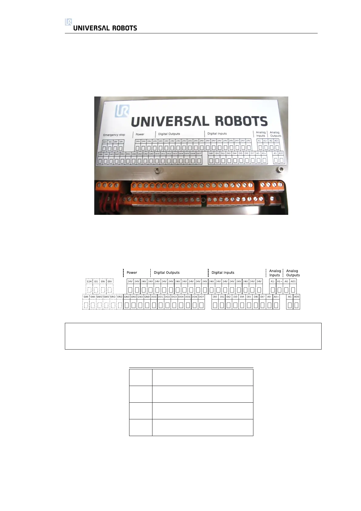
Inside the controller box there is a panel of screw terminals with various I/O parts,
as shown above. The leftmost part of this panel is used for the emergency stop
functionality, as shown below.
Note that any change in the emergency stop circuitry can lead to a dangerous
robot condition, even though the robot emergency stop functionality seems to
be present. Never combine the emergency stop circuit with the normal I/O.
The abbreviations of the I/O panel are explained in table 2.3.
24V 24V power supply
GND 0V GND connection
DOx Digital output number x
DIx Digital input number x
AOx Analog output number x plus
AG Analog output GND
Ax+ Analog input number x plus
Ax- Analog input number x minus
Table 2.3: Abbreviations for the I/O interface inside the controller box.
To get a good understanding of the I/O interface, a simplified version of the
internal circuitry is shown below.
22 UR-6-85-5-A

 Loading...


