2.4. Controller I/O
Parameter Min Typ Max Unit
Valid output voltage in current mode 0 - 10 V
Valid output current in voltage mode -20 - 20 mA
Short-circuit current in voltage mode - 40 - mA
Output resistance in voltage mode - 43 TBD ohm
Offset error @ 4mA, load = 500ohm - - TBD mA
Total error @ 20mA, load = 500ohm - - TBD mA
Offset error @ 0V, load = 1Mohm - 0.5 TBD mV
Total error @ 5V, load = 1Mohm - 50 TBD mV
Table 2.7: Data specification of analog outputs. TBD = To Be Determined.
Note that if the robot on the left side of the illustration is turned off, the input
signal of the right robot will be high, and this can lead to unexpected behavior.
Combining the emergency stop circuitry between the robots should be consid-
ered to avoid these situations.
2.4.3 Analog Outputs
The analog outputs can be set for both current mode and voltage mode, in the
range of 4-20mA and 0-5V respectively. The analog outputs are limited by the
data shown in table 2.7.
To illustrate clearly how easy it is to use analog outputs, some simple exam-
ples are shown.
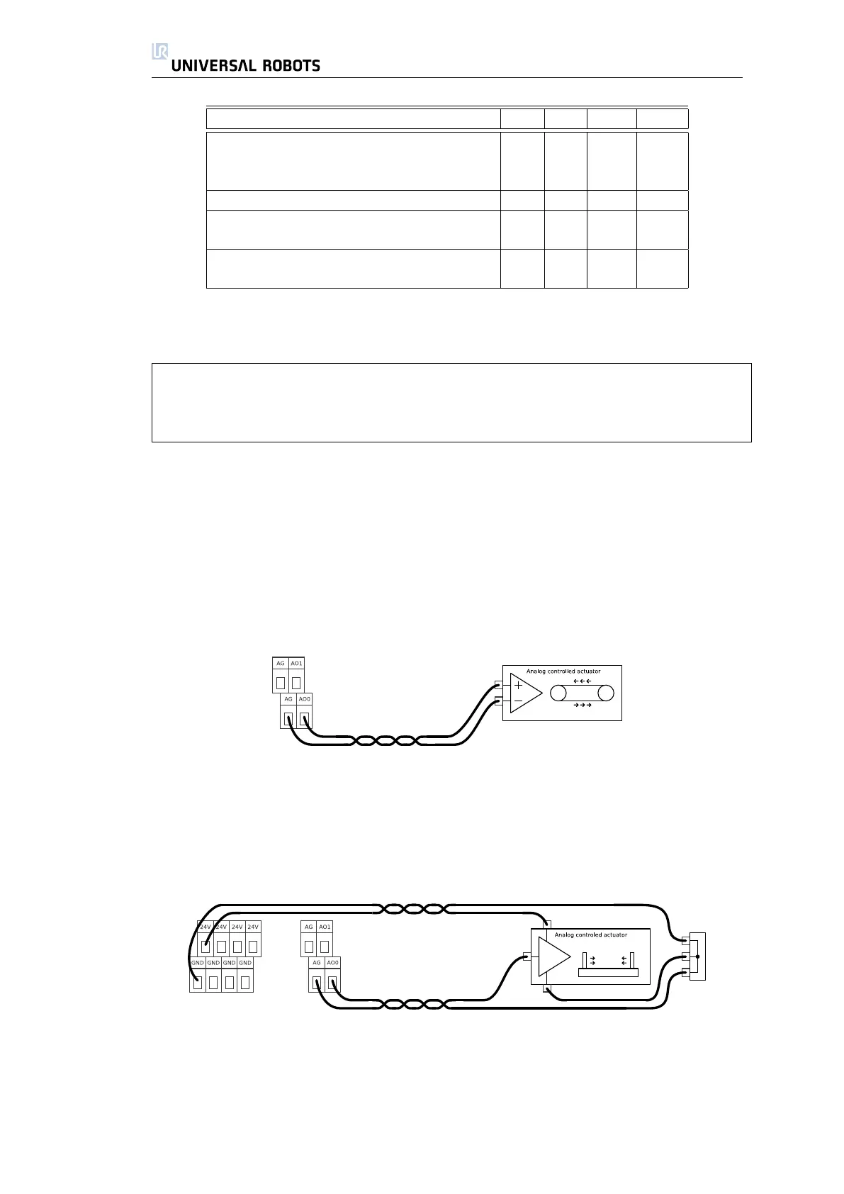
Using the Analog Outputs
This is the normal and best way to use analog outputs. The illustration shows
a setup where the robot controller controls an actuator like a conveyor belt.
The best result is accomplished when using current mode, because it is more
immune to disturbing signals.
Using the Analog Outputs, Non-Differential Signal
If the controlled equipment does not take a differential input, an alternative
solution can be made as shown above. This solution is not very good in terms of
noise, and can easily pick up disturbing signals from other machinery. Care must
be taken when the wiring is done, and it must be kept in mind that disturbing
signals induced into analog outputs may also be present on other analog I/O.
26 UR-6-85-5-A

 Loading...


