2.4. Controller I/O
Parameter Min Typ Max Unit
Voltage available at connection 24V TBD 24 TBD V
Current available at connection 24V - - 800* mA
Short-circuit current protection - 850 - mA
Capacitive load at connection 24V - - TBD uF
Inductive load at connection 24V - - TBD uH
Table 2.4: Normal I/O interface data. TBD = To Be Determined.
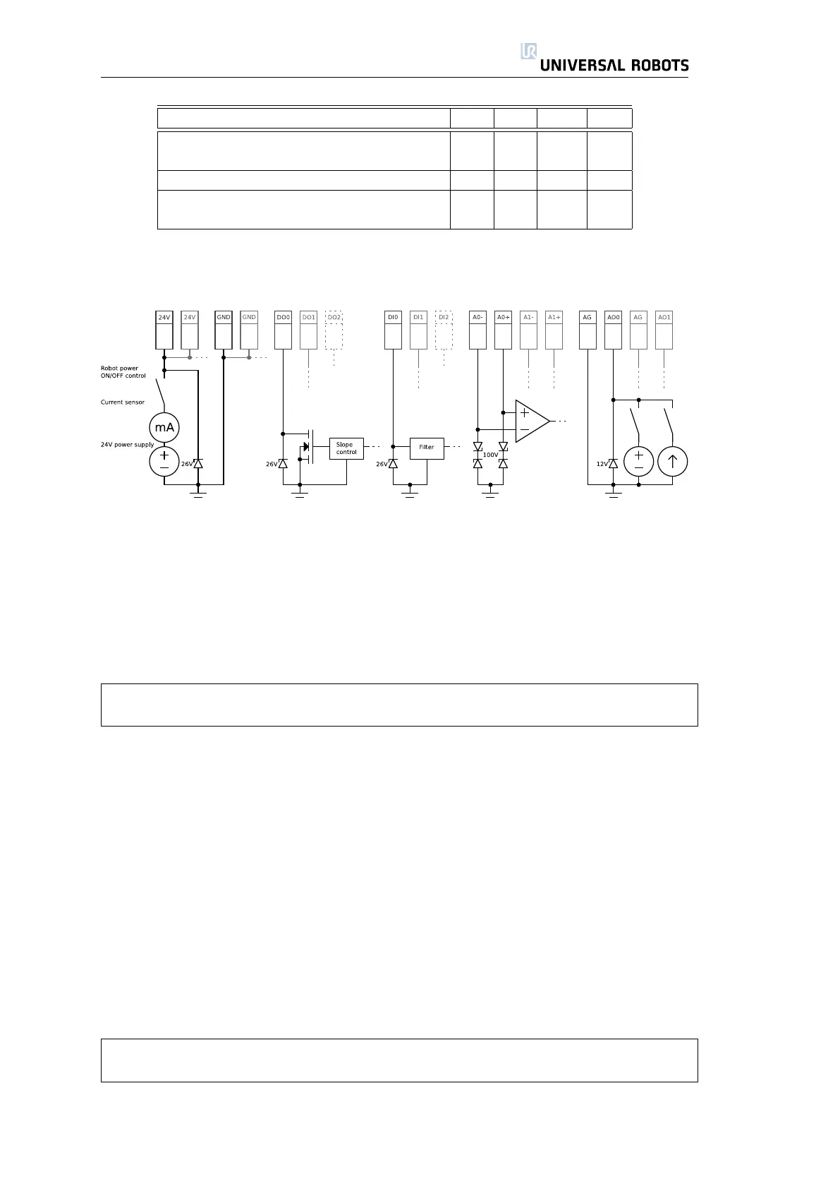
The left part shows the general purpose 24V power supply, which the user
can use for basic controlling and powering. Note that the 24V is only turned
on when the robot is turned on. This also means that if an operator pushes
the emergency stop button, then the power disappears. Just remember that
the 24V may not source or control any functions which can lead to dangerous
situations according to the risk assessment.
The general data on the 24V power supply is shown in table 2.4.
Note that connection E24 is sourced by the same internal 24V regulator as the
normal I/O, and that the maximum of 800mA is for both power sources together.
The internal control system will power off the robot if the current exceeds its
limit. This will also generate an error message in the robot log. The next subsec-
tions show some simple examples of how to use the different I/O functionalities.
2.4.1 Digital Outputs
The digital outputs are implemented so that they can only sink to GND (0V)
and not source current. When a digital output is activated, the corresponding
connection is driven to GND, and when it is deactivated, the corresponding
connection is open (open-collector/open-drain). The advantage of this imple-
mentation is that it is possible to use any external power supply instead of the
internal 24V power supply, as long as its voltage is not higher than the specified
limit.
The digital outputs are limited by the data specified in table 2.5.
Note that the digital outputs are not current limited and overriding the specified
data can cause permanent damage.
To illustrate clearly how to use the digital output ports, some simple examples
are shown.
23 UR-6-85-5-A

 Loading...


