2.5. Tool I/O
Parameter Min Typ Max Unit
Input voltage in voltage mode -0.5 - 26 V
Input voltage in current mode -0.5 - 5.0 V
Input current in current mode -2.5 - 25 mA
Input resistance @ range 0V to 5V - 29 - kohm
Input resistance @ range 0V to 10V - 15 - kohm
Input resistance @ range 4mA to 20mA - 200 - ohm
Offset error @ Range 0 - 5 - TBD TBD mV
Offset error @ Range 0 - 10 - TBD TBD mV
Offset error @ Range 4mA to 20mA - TBD TBD mA
Total error @ Range 0 - 5 - TBD TBD mV
Total error @ Range 0 - 10 - TBD TBD mV
Total error @ Range 4mA to 20mA - TBD TBD mA
Table 2.13: Data specification of analog inputs. TBD = To Be Determined.
time of the two conducting surfaces. However, in most programs it will not cause
problems.
2.5.3 Analog Inputs
The analog inputs at the tool are very different from those inside the controller
box. The first ting to notice is that they are non-differential, which is a drawback
compared to the analog inputs at the controller I/O. The second thing to no-
tice is that the tool analog inputs have current mode functionality, which is an
advantage compared with the controller I/O. The analog inputs can be set to
different input ranges, which are implemented in different ways, and therefore
can have different offset and gain errors. The data specification of the analog
inputs is shown in Table 2.11.
An important thing to realize is that any current change in the common GND
connection can result a disturbing signal in the analog inputs, because there will
be a voltage drop along the GND wires and inside connectors.
Note that a connection between the tool power supply and the analog inputs
will permanently damage the I/O functionality, if the analog inputs are set in
current mode.
To make it clear how easy it is to use digital inputs, some simple examples are
shown.
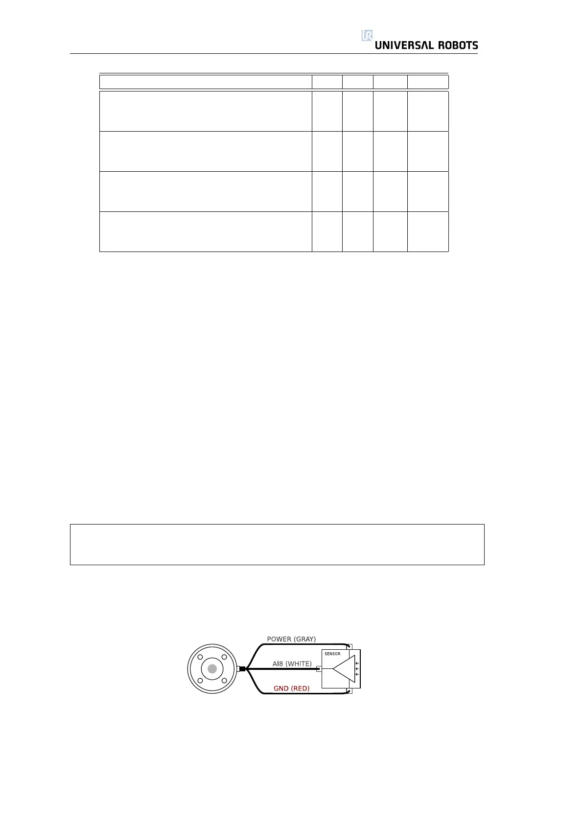
Using Analog Inputs, Non-differential
The simplest way to use analog inputs. The output of the sensor can be either
current or voltage, as long as the input mode of that analog input is set to the
same on the I/O tab (see section 3.3.2). Remember to check that a sensor with
voltage output can drive the internal resistance of the tool, or the measurement
might be invalid.
31 UR-6-85-5-A

 Loading...


