3.4. Programming
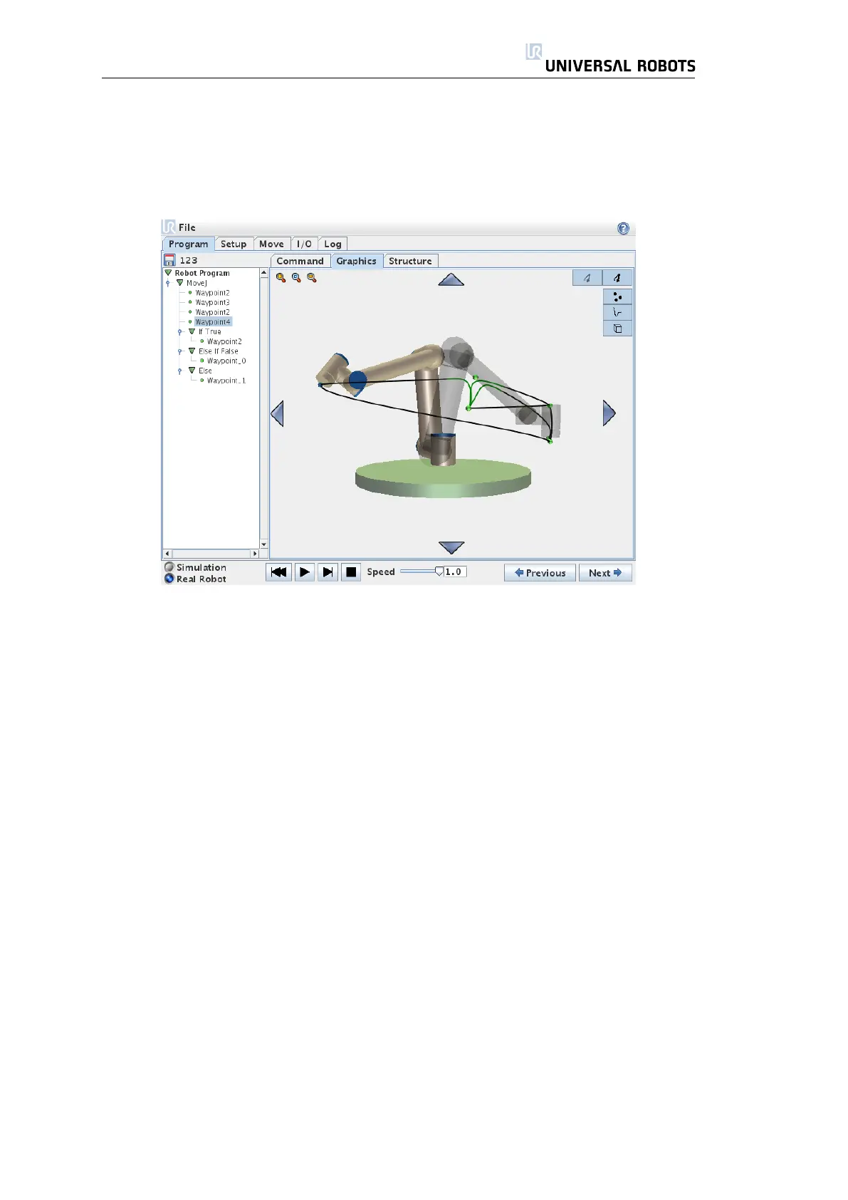
3.4.24 Program → Graphics Tab
Graphical representation of the current robot program. The path of the TCP
is shown in the 3D view, with motion segments in black, and blend segments
(transitions between motion segments) shown in green. The green dots specify
the positions of the TCP at each of the waypoints in the program. The 3D draw-
ing of the robot shows the current position of the robot, and the “shadow” of
the robot shows how the robot intends to reach the waypoint selected in the
left hand side of the screen.
The 3D view can be zoomed and rotated to get a better view of the robot.
The buttons in the top-right side of the screen can disable the various graphical
components in the 3D view.
The motion segments shown depends on the selected program node. If a
Move node is selected, the displayed path is the motion defined by that move.
If a Waypoint node is selected, the display shows the following ∼ 10 steps of
movement.
67 UR-6-85-5-A

 Loading...


