2.4. Controller I/O
Parameter Min Typ Max Unit
Input voltage -0.5 - 26 V
Logical low voltage - - 2.0 V
Logical high voltage 5.5 - - V
Input resistance - 47k - ohm
Table 2.6: Data specification of digital inputs.
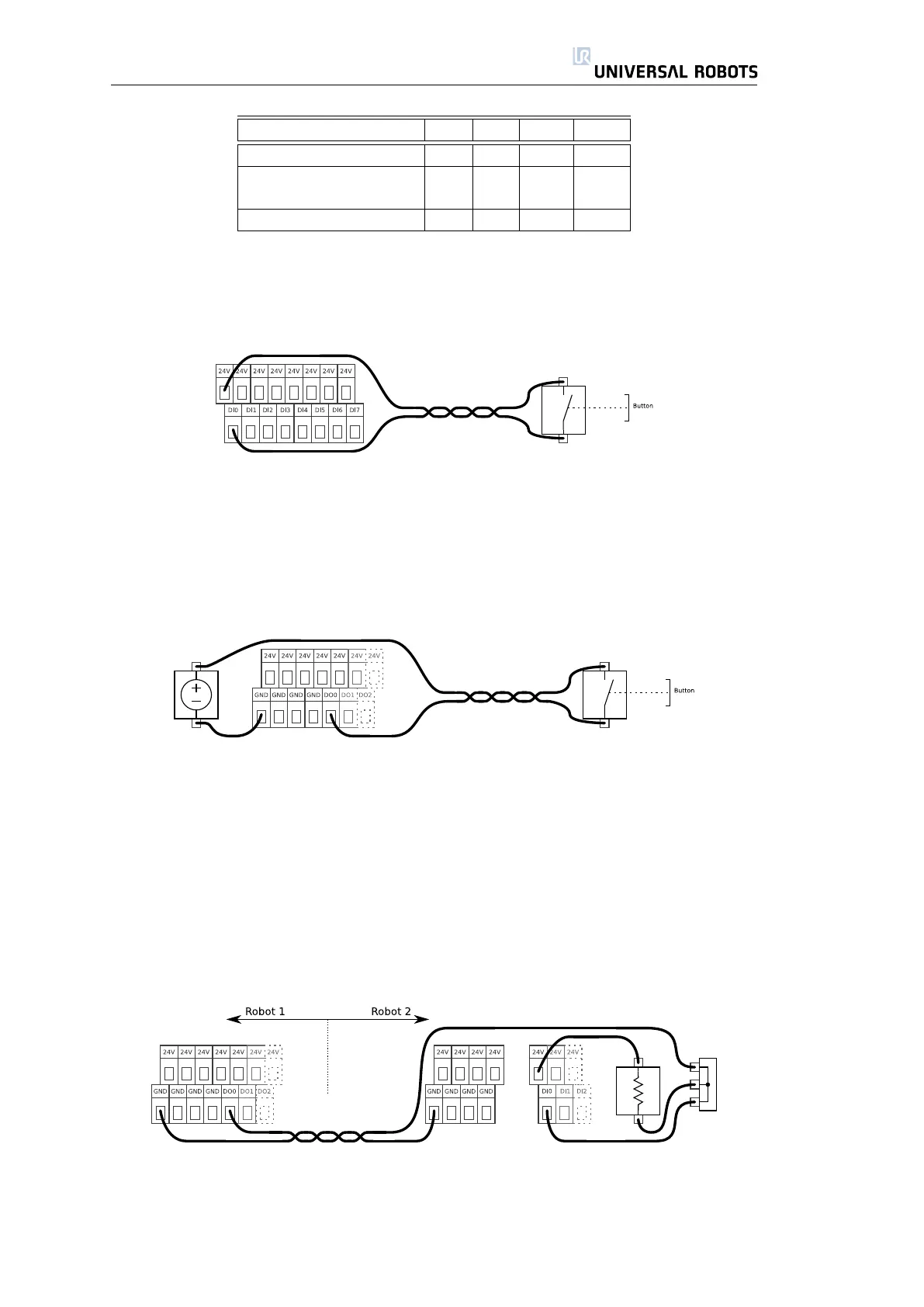
Digital Input, Simple Button
The above example shows how to connect a simple button or switch. A bad
quality switch might trigger the input twice due to a long mechanical stabilizing
time of the two conducting surfaces. However, in most programs it will not cause
problems.
Digital Input, Simple Button
The above illustration shows how to connect a button using an external power
source. Remember that table 2.6 specifies the valid supply voltage for this case.
Signal Communication with other Machinery or PLCs
If communication with other machinery or PLCs is needed, and the signal driver
is both sinking and sourcing, communication is done by direct wiring. Since the
digital outputs of a UR robot are only sinking, a pull-up resistor is needed. An
example where two UR robots are communicating with each other is illustrated
below.
The UR robot on the left side is communicating with the robot on the right side.
A typical value for the resistor shown is 10kohm. The three-terminal box is just a
terminal strip.
25 UR-6-85-5-A

 Loading...


