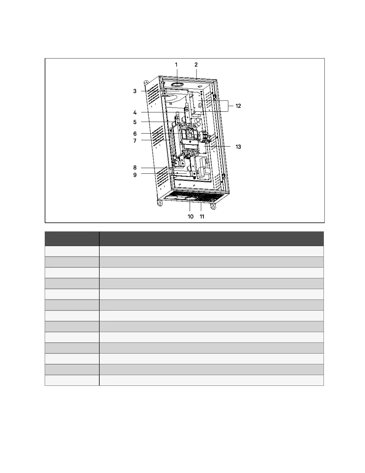
Figure 7.4 Internal structu re of BC B box (400 A )
N O. Description
1 Top cable entry hole
2 Top plate
3 Current transformer of battery ground fault detector
4 Battery terminal (-)
5 Battery terminal (+)
6 BCB
7 Grounding bar
8 UPS terminal (+)
9 UPS terminal (-)
10 Bottom cable entry hole
11 Bottom plate
12 Battery switch control board
13 PCB of battery ground fault detector
7 Battery
132
Vertiv™ Liebert® EXM2 UPS User Manual