Dim ensions (H x W x D), m m W eight (kg)
650 × 1000 × 285 64
Table 7.3 P aram eters of BCB box
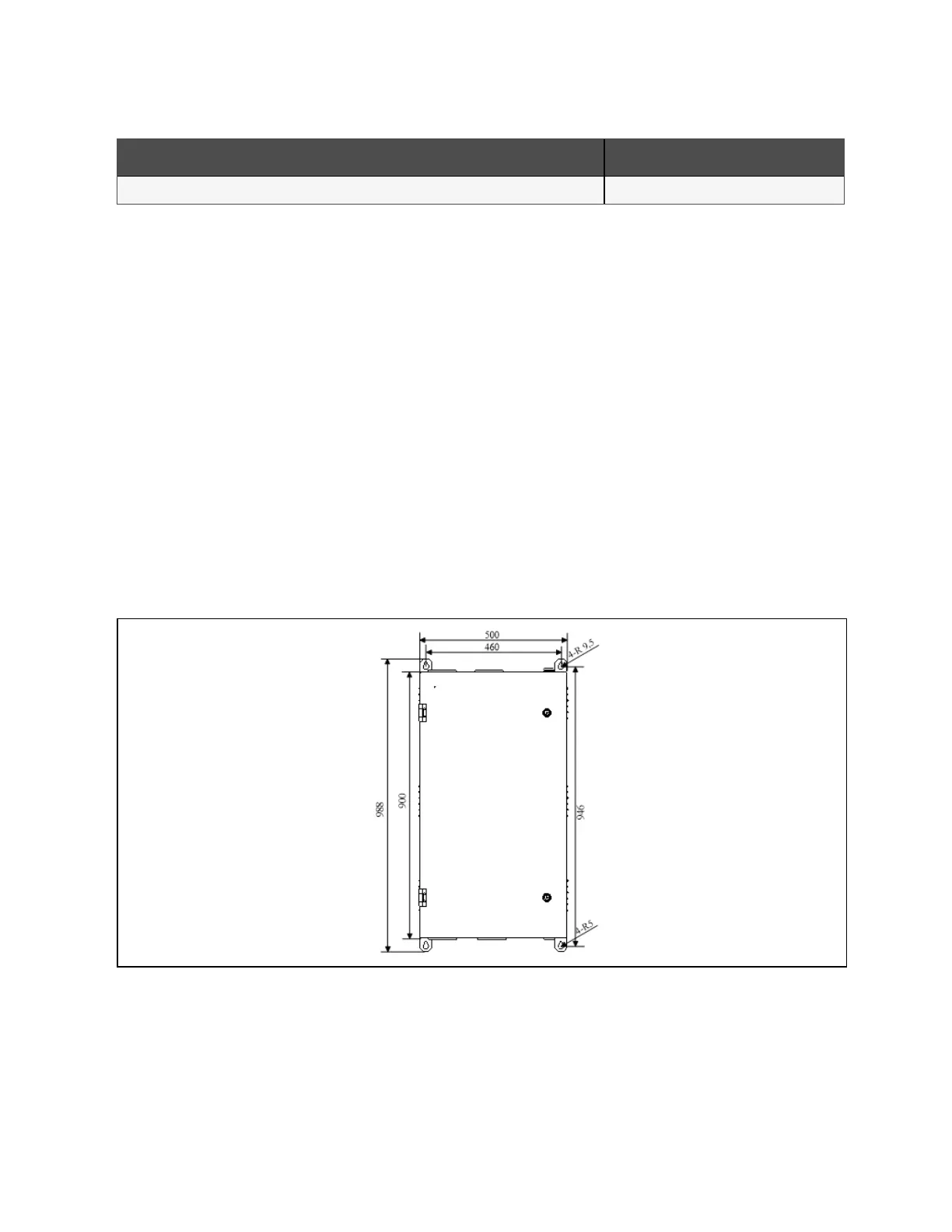
The BCB box should be installed as close as possible to the battery. It can be installed on a wall or a horizontal surface through
the installation holes shown in Figure 7.3 below. The maximum length of signal cable from the battery switch box to UPS is
30m. Cable length limits should be taken into account during installation.
Refer to Figure 7.3 below ~ Figure 7.5 on page133 to install and connect the BCB box. There are connection terminals in the
BCB box for connecting the power cables from the UPS and battery. For signal cable connection, connect the accessory cable
W812 shown in Figure 7.5 on page133.
N O T E: T he B C B box can use top cable entry and bottom cab le entry. It p rovid es a big and a sm all
cable entry holes on both the top plate and bottom plate. T he big ones are for p ow er cable entry
w hile th e sm all one is for signal cable entry. A fter connection, take appropriate m easures to seal the
cable entry holes.
N O T E: T he signal cable m ust run separate from the battery power cables. T he signal cable is a shield
cable, both ends of its shield layer m ust be connected to the enclosure. The U PS and BC B box m ust
be earthed separately.
N O T E: T he B C B box should be in stalled next to the battery and the w o rking tem peratu re is 0 ~ 40
o
C.
Figure 7.3 Installation hole d im ension of BCB box (4 0 0A )
7 Battery
131
Vertiv™ Liebert® EXM2 UPS User Manual