Side C abinet m echanical connectio n
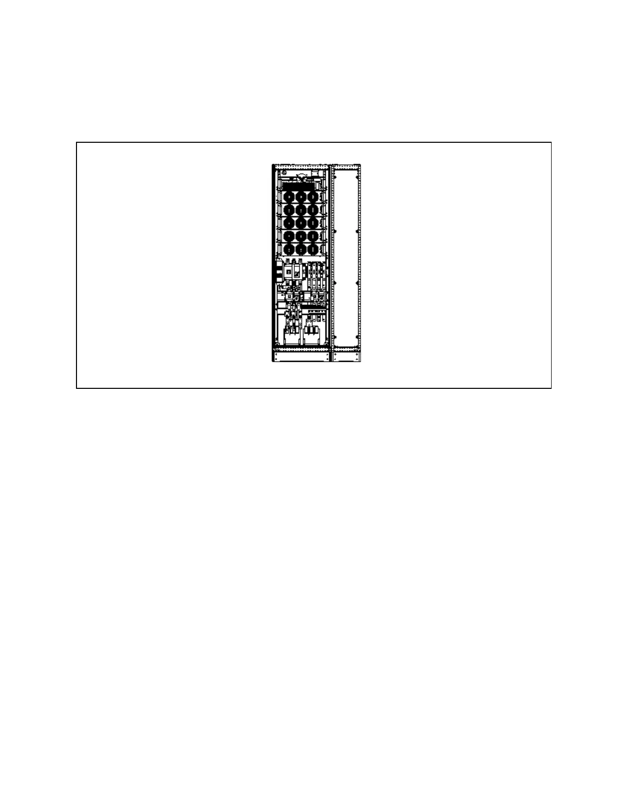
The power cabinet and optional side cabinet need to be connected at installation site, see Figure 9.2 below.
Figure 9.2 M echanical cabinet conn ection
N O T E: W hen installing the two cabinets, rem ove th e right-sid e panel of the m ain pow er cabin et first,
and install the dism antled right-side panel on the rig ht-side of the top cabling cabinet after the top
cabling cabin et is installed.
Side cabinet electrical connection
1. See Figure 9.3 on the next page, taking 250kVA module as an example.
N O T E: T he pow er cables should be routed throug h tunnels or cable troughs to prevent cable dam age
due to m echanical stress.
N O T E: W hen routing the cables insid e the cabinets, it is required to bind an d fix the cables as
instructed in Figure 9.3 on the next page in the cabinets, so as to prevent cable dam age d ue to
m echanical stress.
9 Options
155
Vertiv™ Liebert® EXM2 UPS User Manual