EasyManuals Logo

Vertiv NetSure 5100 Series Installation Manual

Vertiv NetSure 5100 Series
178 pages
To Next Page IconTo Next Page
To Previous Page IconTo Previous Page
Page #117 background imageLoading...
Page #117 background image
Vertiv™ NetSure™ 5100 Series -48 VDC Power System Installation Manual
Proprietary and Confidential © 2023 Vertiv Group Corp.
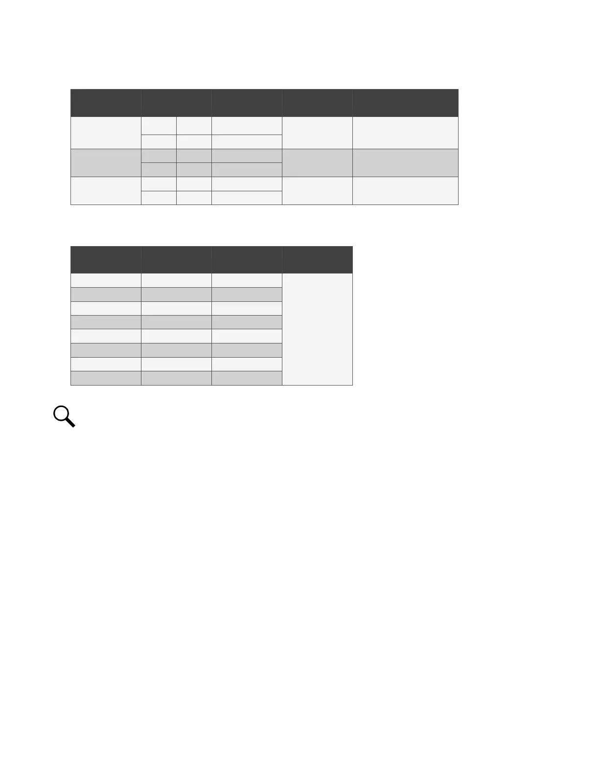
109
Table 5.5 Shunt Inputs EIB
Shunt
Input
EIB
Pin No.
Factory
Wiring
Default
Function
Customer
Defined Function
Sh1
J5-2 + --
none
J5-1 --
Sh2
J5-4 + --
none
J5-3 --
Sh3
J5-6 + --
none
J5-5 --
Table 5.6 Voltage Inputs EIB
Voltage
Input
EIB
Pin No.
Factory
Wiring
Default
Function
1 J6-1 --
Battery
Block
Monitoring
2 J6-2 --
3 J6-3 --
4 J6-4 --
5 J6-5 --
6 J6-6 --
7 J7-1 --
8 J7-3 --
NOTE!
The output relay configuration may not be set according to the factory default setting. Refer to the configuration
drawing (C-drawing) supplied with your system for your system’s specific configuration.

Table of Contents

Other manuals for Vertiv NetSure 5100 Series

Questions and Answers:

Question and Answer IconNeed help?

Do you have a question about the Vertiv NetSure 5100 Series and is the answer not in the manual?

Vertiv NetSure 5100 Series Specifications

General IconGeneral
BrandVertiv
ModelNetSure 5100 Series
CategoryPower Supply
LanguageEnglish

Related product manuals