Vertiv™ NetSure™ 5100 Series -48 VDC Power System Installation Manual
Proprietary and Confidential © 2023 Vertiv Group Corp.
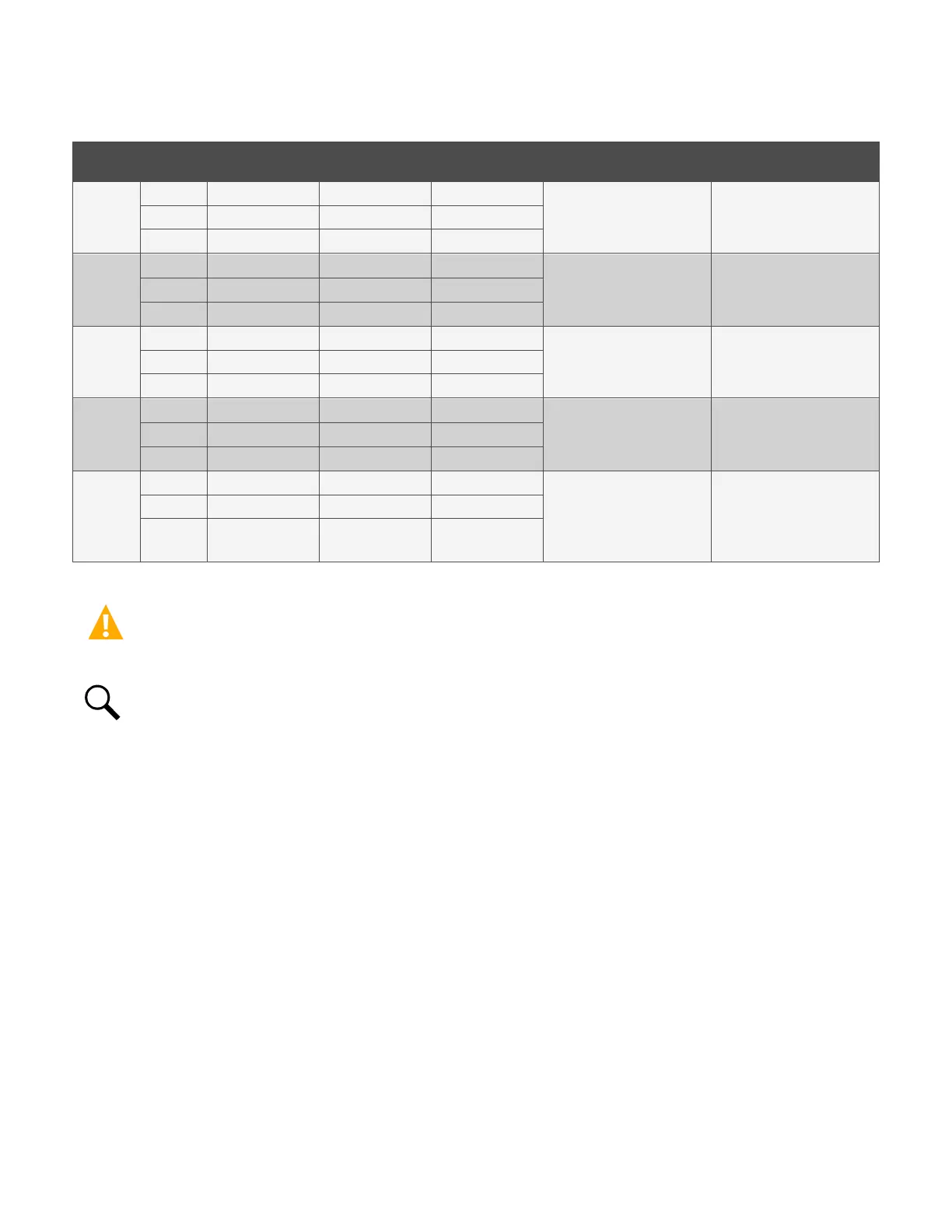
Table 5.7 Relay Outputs (Factory Default) – EIB
Programmable Relay
Output
EIB
Pin No.
541309 Alarm Cable
Color Scheme
Factory
Wiring
Alarms Assigned to this Relay
(Default)
Alarms Assigned to this Relay
(Custom)
1
NO
J8-5
W-BL --
-- COM
J8-3
BL-W --
NC J8-1 W-O --
2
NO
J8-6
O-W --
-- COM
J8-4
W-G --
NC
J8-2
G-W --
3
NO
J9-5
W-BR --
-- COM
J9-3
BR-W --
NC J9-1 W-S --
4
NO
J9-6
S-W --
-- COM
J9-4
R-BL --
NC
J9-2
BL-R --
5
NO
J7-6
-- --
Critical Alarm
COM J7-4 -- Resistive Battery
NC J7-2 --
Optional Critical
Alarm LED
CAUTION! All conductors in this harness may be connected within the cabinet. Shorting or grounding of unused conductors
may result in service interruption or equipment damage. Therefore insulate all conductor ends not being used in your
application.
NOTE!
The relays energize during an alarm condition, closing the contacts between the C and NO terminals, and opening
the contacts between the C and NC terminals.

 Loading...


