Vertiv™ NetSure™ 5100 Series -48 VDC Power System Installation Manual
Proprietary and Confidential © 2023 Vertiv Group Corp.
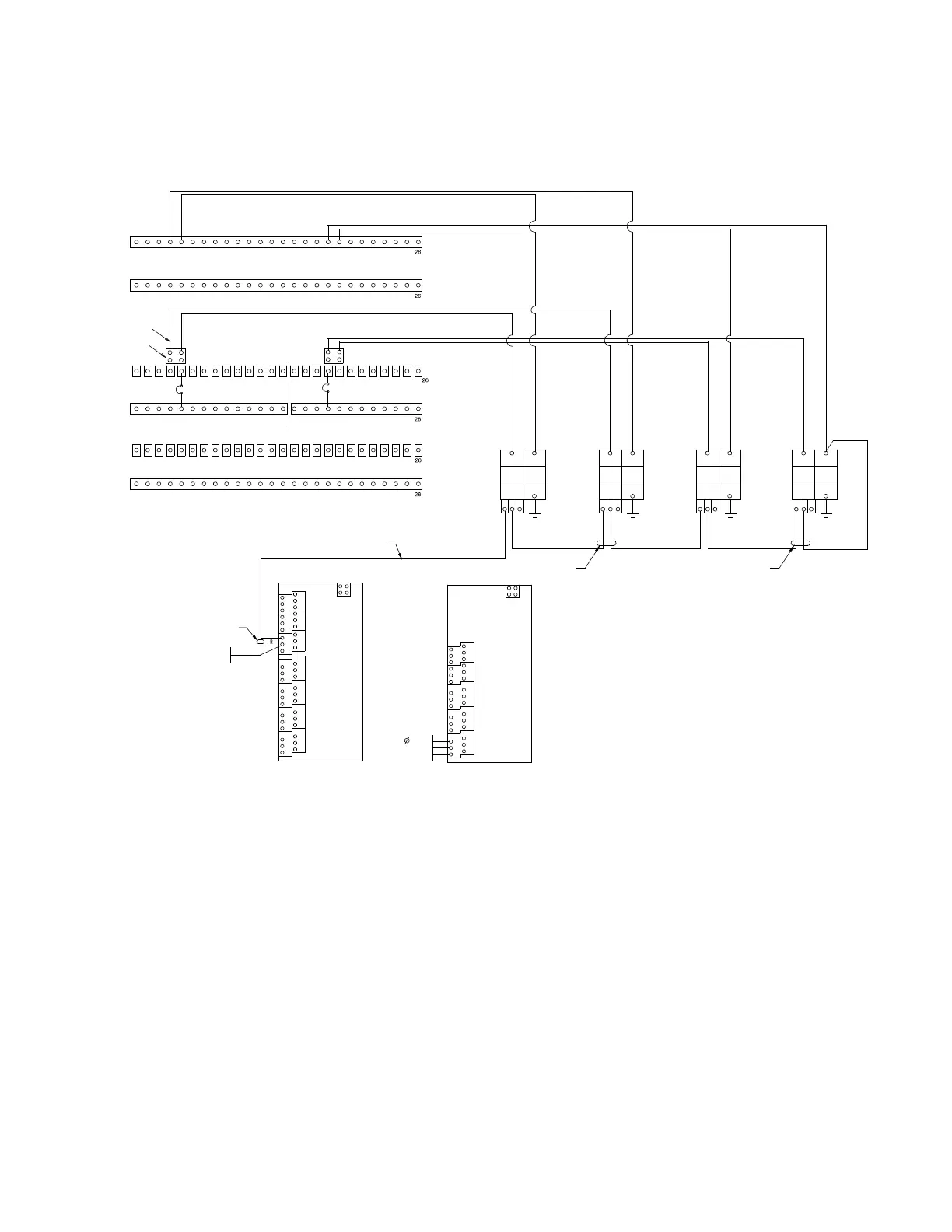
Figure 3.31 P/N 60051981 Surge Protection Device (SPD) Field Installation Kit Power and Alarm Wiring Diagram for-48 VDC and
-58 VDC Power System
[ ] 4. Install the kit supplied DIN rail per site requirements. The SPDs will be mounted to the DIN rail. Typically install the DIN
rail onto the enclosure the power system is mounted in. Customer must supply the DIN rail mounting hardware. Take
the following into considerations when choosing a DIN rail mounting location:
- Wire lengths for “+”, “-“, and “Earth Ground” must be minimized.
- Tight bends in 6 AWG wire (less than 2” radius) must be avoided.
[ ] 5. Slide the kit supplied SPD devices onto the DIN rail and secure at each end with a kit supplied DIN rail end clamp.
Recommended torque for DIN rail end clamps is 15 in-lbs.
- Note that for kit P/N 60056702 the two SPD devices are installed next to each other. See Figure 3.32 for a diagram.
- Note that for kit P/N 60051981, two SPD devices are installed next to each other, then a DIN rail end clamp is
installed and then the remaining two SPD devices are installed next to each other. See Figure 3.33 for a diagram.
Note: For 582137100500 or a 582137100ZZ028 plant that has been converted to a 582137100500 plant Only
RETURN LOAD ROW 2
RETURN LOAD ROW 1
-48 VDC LOAD OUTPUT ROW 1
-48 VDC LOAD INPUT ROW 1
-48 VDC LOAD OUTPUT
ROW 2
-48 VDC LOAD INPUT ROW 2
-58 VDC LOAD OUTPUT ROW 2
-58 VDC LOAD INPUT ROW 2
1
4 5 18 19
1
1
1
1
1
CB1
P/N 101609 75 A
CIRCUIT BREAKER
CB2
P/N 101609 75 A
CIRCUIT BREAKER
SPD 1
P/N 10034885
SURGE
PROTECTION
DEVICE
SPD 2
P/N 10034885
SURGE
PROTECTION
DEVICE
SPD 3
P/N 10034885
SURGE
PROTECTION
DEVICE
SPD 4
P/N 10034885
SURGE
PROTECTION
DEVICE
6 AWG / RTN / BK
6 AWG / RTN / BK
6 AWG / RTN / BK
6 AWG / RTN / BK
6 AWG / -58V / BL
6 AWG / -58V / BL
6 AWG / -48V / BL
6 AWG / -48V / BL
BL
6 AWG (G) 6 AWG (G) 6 AWG (G) 6 AWG (G)
BL
BL
BL
MAKE FROM P59888A
24 AWG (BL/W)
/ -48V /
R-W
P/O 60056635 SPD
ALARM JUMPERS
J3
J4
J5
J6
J7
J8
J9
1
2
3
4
5
6
1
2
3
4
5
6
1
2
3
4
5
6
J2
-
+
DI1
DI2
DI3
DI4
DI5
DI6
DI7
DI8
NC
C
NO
DO8
NC
C
NO
D07
NC
C
NO
DO6
NC
C
NO
D05
NC
C
NO
DO4
NC
C
NO
D03
NC
C
NO
DO2
NC
C
NO
D01
MA4C5U31
IB2 BOARD
DIGITAL
INPUTS
RELAY OUTPUTS
J5 SHUNT INPUTS
J6 VO LTAGE
INPUTS
J7 RELAY
13 &
VOLTAGE
INPUTS
J8 RELAYS 9 & 10
J9 RELAYS 11 & 12
-
-
-
J2
+
+
+
V1
V3
V5
V2
V4
V6
V7
V8
NC
C
NO
DO5
NC
C
NO
D02
NC
C
NO
DO1
NC
C
NO
DO4
NC
C
NO
D03
MA455U41
EIB BOARD
SURGE
PROTECTION
DEVICE FAIL
1
2
3
12 11 14
(-) (+)
PE
12 11 14
(-) (+)
PE
12 11 14
(-) (+)
PE
12 11 14
(-) (+)
PE
P/O 60056635 SPD
ALARM JUMPERS
P/O 60056635 SPD
ALARM JUMPERS
Load output bars and return bars have two hole lug landing points. Single hole shown in image for clarity only.
4
5
18
19
1-POLE ADAPTER KIT
P/N 559803 (4-PLACES)
2-LUG PLATE ADAPTER
P/N 60016097 (2-PLACES)
Earth Ground Earth Ground Earth Ground Earth Ground
To Main Ground
Busbar
To Main Ground
Busbar
To Main Ground
Busbar
To Main Ground
Busbar

 Loading...


