Vertiv™ NetSure™ 5100 Series -48 VDC Power System Installation Manual
Proprietary and Confidential © 2023 Vertiv Group Corp.
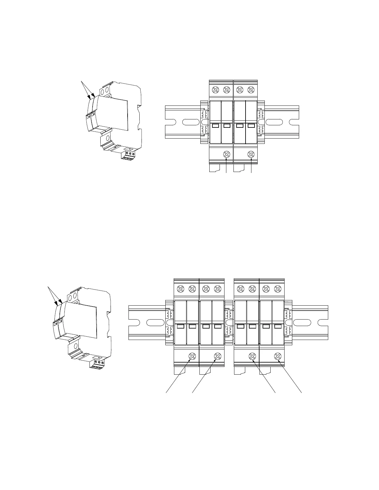
Figure 3.32 Install SPD Devices to DIN Rail Kit P/N 60056702
Figure 3.33 Install SPD Devices to DIN Rail Kit P/N 60051981
SPDs Mounted
External to
Power System
SPD1 SPD2
(-) (+) (-) (+)
Front View
To Main Ground
Busbar (Earth Ground)
To Main Ground
Busbar (Earth Ground)
SPD Ground
Lug Location
SPD Ground
Lug Location
6 AWG (G) 6 AWG (G)
Ground Cable Terminals Recommended Torque: 30 in-lbs.
SPD Side View
Snap-Out DC SPD
(Surge Protection
Device) Modules
Power Cable Terminals
Recommended Torque: 30 in-lbs.
Alarm Contacts Terminals
Recommended Torque: 2.2 in-lbs.
Power Cable Terminals
Recommended Torque: 30 in-lbs.
A
larm Contacts Terminals
Recommended Torque: 2.2 in-lbs.
SPDs Mounted
External to
Power System
Front View
-48VDC/Return -58VDC/Return
SPD1 SPD2 SPD3 SPD4
(-) (+) (-) (+) (-) (+) (-) (+)
SPD Side View
Snap-Out DC SPD
(Surge Protection
Device) Modules
To Main Ground
Busbar (Earth Ground)
To Main Ground
Busbar (Earth Ground)
SPD Ground
Lug Location
SPD Ground
Lug Location
6 AWG (G) 6 AWG (G)
To Main Ground
Busbar (Earth Ground)
To Main Ground
Busbar (Earth Ground)
SPD Ground
Lug Location
SPD Ground
Lug Location
6 AWG (G) 6 AWG (G)
Ground Cable Terminals Recommended Torque: 30 in-lbs.

 Loading...


