Chapter 9 Deployment CPU 21xSER-1 Manual VIPA CPU 21x
9-20 HB103E - Rev. 05/45
Modbus slave function codes
Modbus has some naming conventions:
Word =
Register
IN: "Input Register"
OUT: "Holding Register"
Bit =
Coil
IN: "Input Status"
OUT: "Coil Status"
• Modbus differentiates between bit and word access;
Bits = "Coils" and Words = "Register".
• Bit inputs are referred to as "Input-Status" and Bit outputs as "Coil-
Status".
• Word inputs are referred to as "Input-Register" and Word outputs as
"Holding-Register".
Normally the access under Modbus happens by means of the ranges 0x,
1x, 3x and 4x.
0x and 1x gives you access to digital bit areas and 3x and 4x to analog
word areas.
For the CPU 21xSER-1 from VIPA is not differentiating digital and analog
data, the following assignment is valid:
0x: Bit area for output
Access via function code 01h, 05h
1x: Bit area for input
Access via function code 02h
3x: Word area for input
Access via function code 04h
4x: Word area for output
Access via function code 03h, 06h, 10h
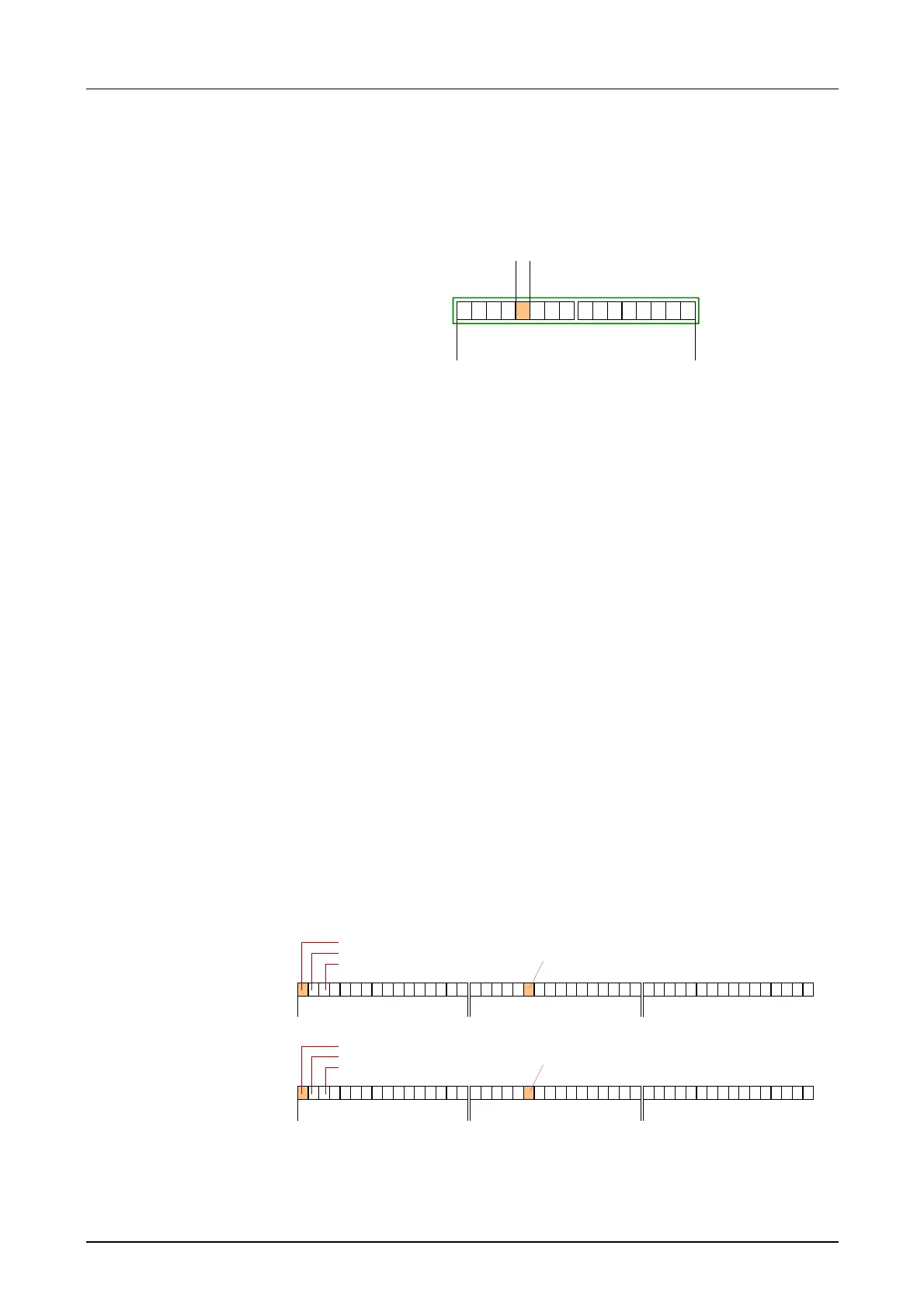
3x
0001
3x
0002
3x
0003
1x
0001
1x
0002
1x
0003
IN
1x
0022
4x
0001
4x
0002
4x
0003
0x
0001
0x
0002
0x
0003
OUT
0x
0022
A description of the function codes follows below.
Naming
convention
Range definitions

 Loading...


