Chapter 7 Deployment of the CPU 21xDP Manual VIPA CPU 21x
7-28 HB103E - Rev. 05/45
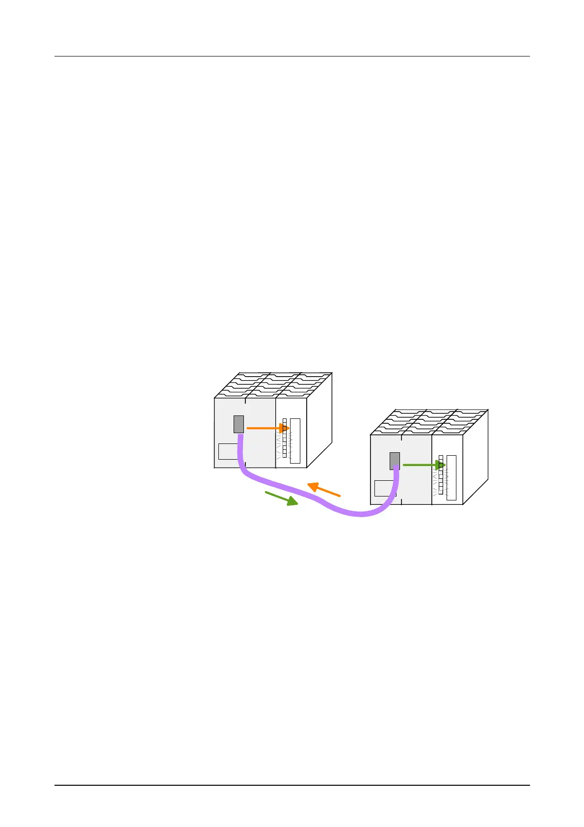
Example
This example is intended to show the communication between a master
CPU 214DPM and a slave CPU 214DP.
The counters are to communicate via the Profibus and to be displayed at
the output module of the respective partner.
The CPU 214DPM shall count from FFh...00h and transfer the count
cyclically into the output area of the Profibus master. The master has then
to transfer this value to the slave of the CPU 214DP.
The value received shall be saved in the peripheral input area of the CPU
and monitored at the output module (at address 0) via the backplane bus.
On the other hand, the CPU 214DP should count from 00h to FFh. This
count shall also be saved in the output area of the CPU slave and be
transferred to the master via Profibus.
This value shall be monitored at the output module (address 0) of the
CPU 214DPM.
CPU 21x DPM
DO 8
C1
C2
Counter C1:
FFh ... 00h
Adr.:4
C1
C2
CPU 21x DP
DO 8
C2
C1
Counter C2:
00h ... FFh
Adr.:3
Master
Slave
CPU 21xDPM
Counter: MB 0 (FFh...00h)
Profibus address: 4
Input area: Address 10 length: 2 Byte
Output area: Address 20 length: 2 Byte
CPU 21xDP
Counter: MB 0 (00h...FFh)
Profibus address: 3
Input area: Address 30 length: 2 Byte
Output area: Address 40 length: 2 Byte
Parameter data: Address 50 length: 24 Byte (fixed)
Diagnostic data: Address 60 length: 6 Byte (fixed)
Status data: Address 100 length: 2 Byte (fixed)
Objective
Detailed
description of the
objective
Configuration data

 Loading...


