Manual VIPA CPU 21x Chapter 1 Principles
HB103E - Rev. 05/45 1-7
General description of the System 200V
• Norm profile head rail 35mm
• Peripheral modules with labeling strip
• Measurements basic module:
Single width: (HxWxD) in mm: 76x25.4x80; in inches: 3x1x3
Double width: (HxWxD) in mm: 76x50.8x80; in inches: 3x2x3
Please note, that you have to plug in the CPU only at plug-in location 1
resp. 1 and 2 (if double width).
12
4
3
PW
ER
RD
BA
IM 253 CAN
ADR.
X5
67
VIPA 253-1CA00
DC24V
+
-
1
2
01
DI 8xDC24V
SM 221
.0
.1
.2
.3
.4
.5
.6
.7
VIPA 221-1BF00
X
2
34
1
2
3
4
5
6
7
8
9
I0
DI 8xDC24V
SM 221
.0
.1
.2
.3
.4
.5
.6
.7
VIPA 221-1BF00
X
2
34
1
2
3
4
5
6
7
8
9
I0
DI 8xDC24V
SM 221
.0
.1
.2
.3
.4
.5
.6
.7
VIPA 221-1BF00
X
2
34
1
2
3
4
5
6
7
8
9
I0
DI 8xDC24V
SM 221
.0
.1
.2
.3
.4
.5
.6
.7
VIPA 221-1BF00
X
2
34
1
2
3
4
5
6
7
8
9
I0
DI 8xDC24V
SM 221
.0
.1
.2
.3
.4
.5
.6
.7
VIPA 221-1BF00
X
2
34
1
2
3
4
5
6
7
8
9
I0
DI 8xDC24V
SM 221
.0
.1
.2
.3
.4
.5
.6
.7
VIPA 221-1BF00
X
2
34
1
2
3
4
5
6
7
8
9
I0
DI 8xDC24V
SM 221
.0
.1
.2
.3
.4
.5
.6
.7
VIPA 221-1BF00
X
2
34
1
2
3
4
5
6
7
8
9
I0
DI 8xDC24V
SM 221
.0
.1
.2
.3
.4
.5
.6
.7
VIPA 221-1BF00
X
2
34
1
2
3
4
5
6
7
8
9
I0
PW
SF
FC
MC
CPU 216
DC
24V
+
-
1
2
RN
ST
MR
X1
MMC
R
S
X2
34
VIPA 216-2BA01
M
P
I
2
PW
SF
FC
MC
CPU 216DP
DC
24V
+
-
1
2
RN
ST
MR
X1
MMC
R
S
X2
34
VIPA 216-2BP02
ER
RD
DE
D
P
M
P
I
2
Clack
• Plug in via CageClamps at the front-facing connector, core cross-
section 0.08...2.5mm
2
resp. 1.5 mm
2
(18pin plug)
• Total isolation of the cables during module changes
• Potential separation of all modules to the backplane bus
• EMC-proof ESD/Burst acc. EN61000-4-2/EN61000-4-4
to Level 3: 8kV/2.5kV
• Shock resistance acc. IEC 60068-2-6 / IEC 60068-2-27 (1G/12G)
• Operating temperature: 0... +60°C
• Storage temperature: -40... +85°C
• Relative humidity: 95% without condensation
• fan-less operation
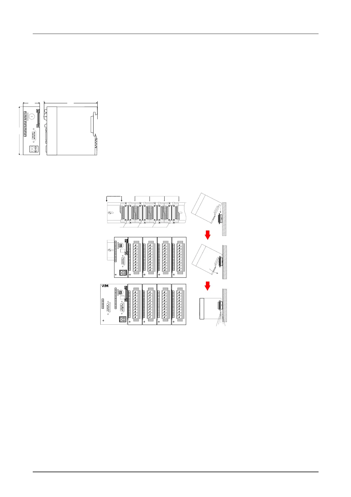
Structure /
Dimensions
Installation
Operating security
Environmental
conditions
[1] CPU if double width
[2] CPU single width
[3] peripheral modules
[4] leading bars
D
W
H
 Loading...


