Chapter 8 Deployment CPU 21xCAN Manual VIPA CPU 21x
8-14 HB103E - Rev. 05/45
Process image of the CPU 21xCAN
The process image is build of the following parts:
• Process image for input data (PI) for RPDOs
• Process image for output data (PO) for TPDOs
Every part consists of 64Byte "Digital-Data"- and 320Byte "Network
Variables".
For input data, the following objects are available:
• 8 Bit digital input (Object 0x6000)
• 16 Bit digital input (Object 0x6100)
• 32 Bit digital input (Object 0x6120)
• 8 Bit input network variables (Object 0xA040)
• 16 Bit input network variables (Object 0xA100)
• 32 Bit input network variables (Object 0xA200)
• 64 Bit input network variables (Object 0xA440)
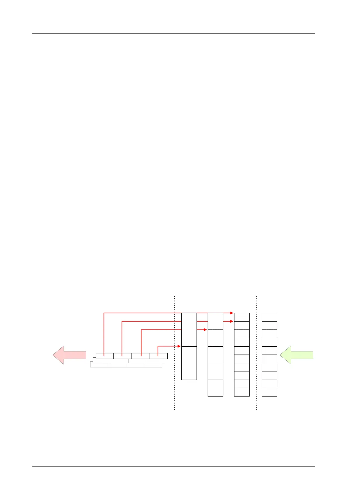
Like to see in the following illustration, the objects of the digital input data
use the same memory area of the CPU.
For example, an access to Index 0x6000 with Subindex 2 corresponds an
access to Index 0x6100 with Subindex 1. Both objects occupy the same
memory cell in the CPU.
Please regard that the input network variables also use the same memory
area.
PDO3
PDO2
PDO1
0
1
2
3
4
0
1
.
.
.
.
.
.
PO
CMS*
WDW
OUT
Mapping
CAN DI
0
1
2
3
4
5
6
7
8
9
.
.
.
CPU
Offset +
0
1
2
3
4
5
6
7
8
9
.
.
.
B
TPDO
PI
*) CMS = CANopen Master/Slave
Input data

 Loading...


