PROCEDURE
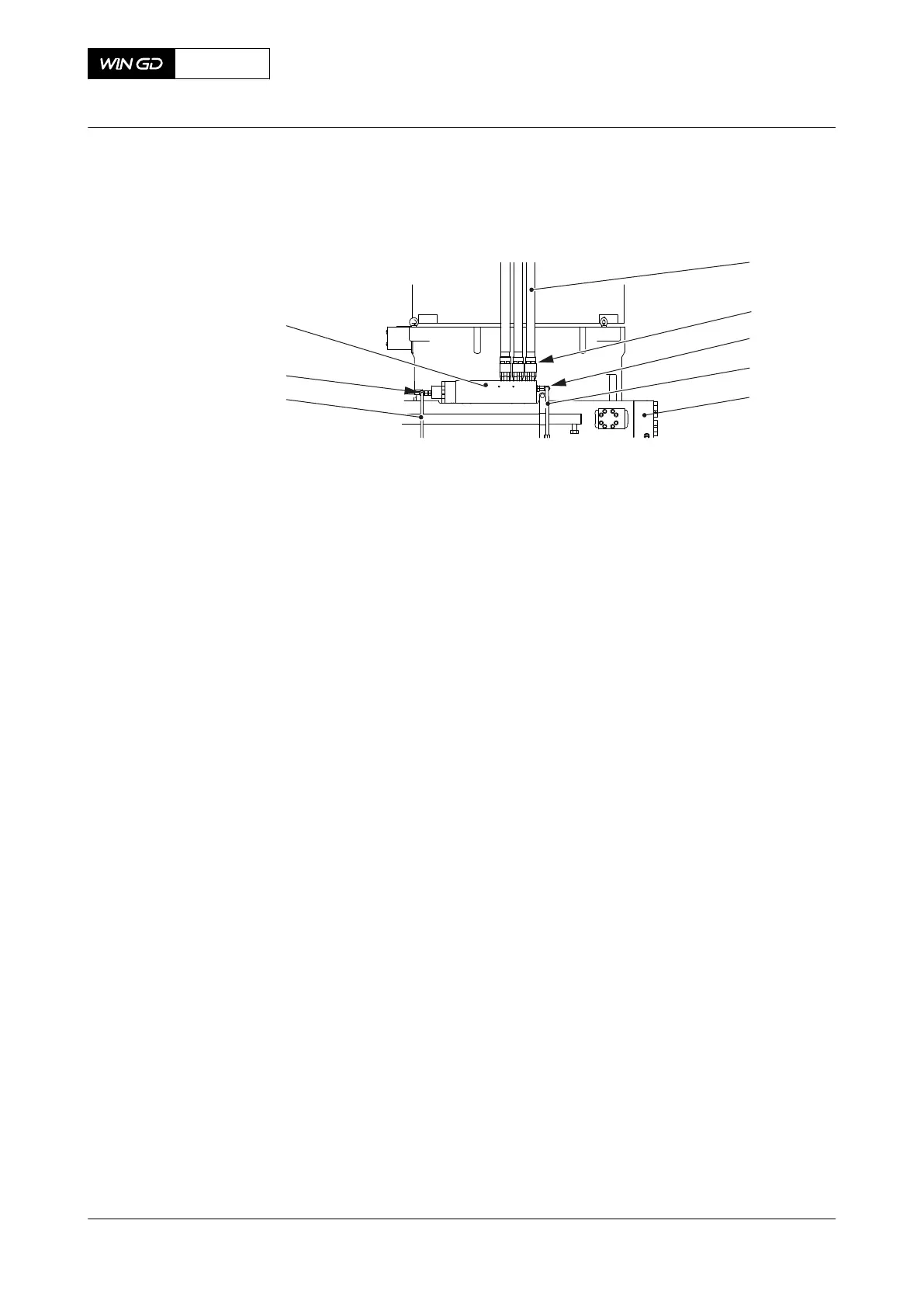
Fig 10-3 Leakage on FLV and pipes (example)
Legend
001 HP fuel pipe to injection valve 005 Fuel rail
002 Screw 006 Fuel leakage pipe
003 Screw-in union 007 Screw-in union
004 Fuel leakage pipe 008 Flow limiting valve (FLV)
1 Do a check of the level switch LS3446A for free flow. If necessary, clean the bore of the
pipe of the level switch.
2 Carefully do a check of the temperature of the fuel leakage pipe (004, Figure 10-3) of each
flow limiting valve (FLV) (008) to find the leakage pipe that has a fuel flow.
NOTE: There is a fuel flow in the leakage pipe that has a higher temperature than the
other leakage pipes.
NOTE: As an alternative you can carefully open and close the screw-in union (003) of
each FLV a maximum of two turns to find the leakage pipe that has a fuel flow.
3 If there is a leakage pipe (004) that has a fuel flow, do as follows:
3.1 Make sure that the screws (002) are tightened correctly, refer to the Maintenance
Manual 8733-1.
3.2 On the fuel leakage pipe (004), carefully loosen the screw-in union (003) a
maximum of two turns.
3.3 Do a check for fuel flow.
3.4 If fuel continues to flow from the screw-in union (003), do as follows (an HP fuel
pipe (001) is defective):
3.4.1 Stop the engine.
3.4.2 Remove each of the HP fuel pipes (001) until you find the defective HP fuel
pipe (refer to the Maintenance Manual 8733-1).
3.4.3 Do a check for damage on the sealing face of the defective HP fuel pipe
(001). If you find damage, grind the sealing face (refer to the Maintenance
Manual 8733-1).
3.4.4 If the HP fuel pipe is defective, cut out the injection of the related cylinder
and replace the defective HP fuel pipe, refer to the Maintenance Manual.
3.4.5 Tighten the screw-in union (003).
3.4.6 Start the engine.
3.5 If no fuel flows from the screw-in union (003), tighten the screw-in union (003).
X72-B
AA00-0000-00AAA-311C-A
Operation Manual Examine the FLV or fuel pipes for fuel leakage
Winterthur Gas & Diesel Ltd.
- 419 - Issue 003 2021-12