13.1 Schematic diagrams - general
NOTE: The diagrams below are part of the Engine-Builder Drawing-Set and are not included in
this operation manual. The diagrams below can be referenced directly in the specific
Engine-Builder Drawing-Set. Please contact your Engine-Builder, if you need the specific
diagrams.
13.1.1 Engine control diagram
The engine control diagram shows data about the control items of the engine and its systems.
In the sub-sections that follow you find general data about the engine control diagram.
13.1.1.1 Area codes in the engine control diagram
The area codes in the engine control diagram are as follows:
•
A - Control air supply unit
•
B - Fuel supply
•
D - Servo oil supply
•
E - Valve unit for start
•
K - Local control panel.
13.1.1.2 Line codes in the engine control diagram
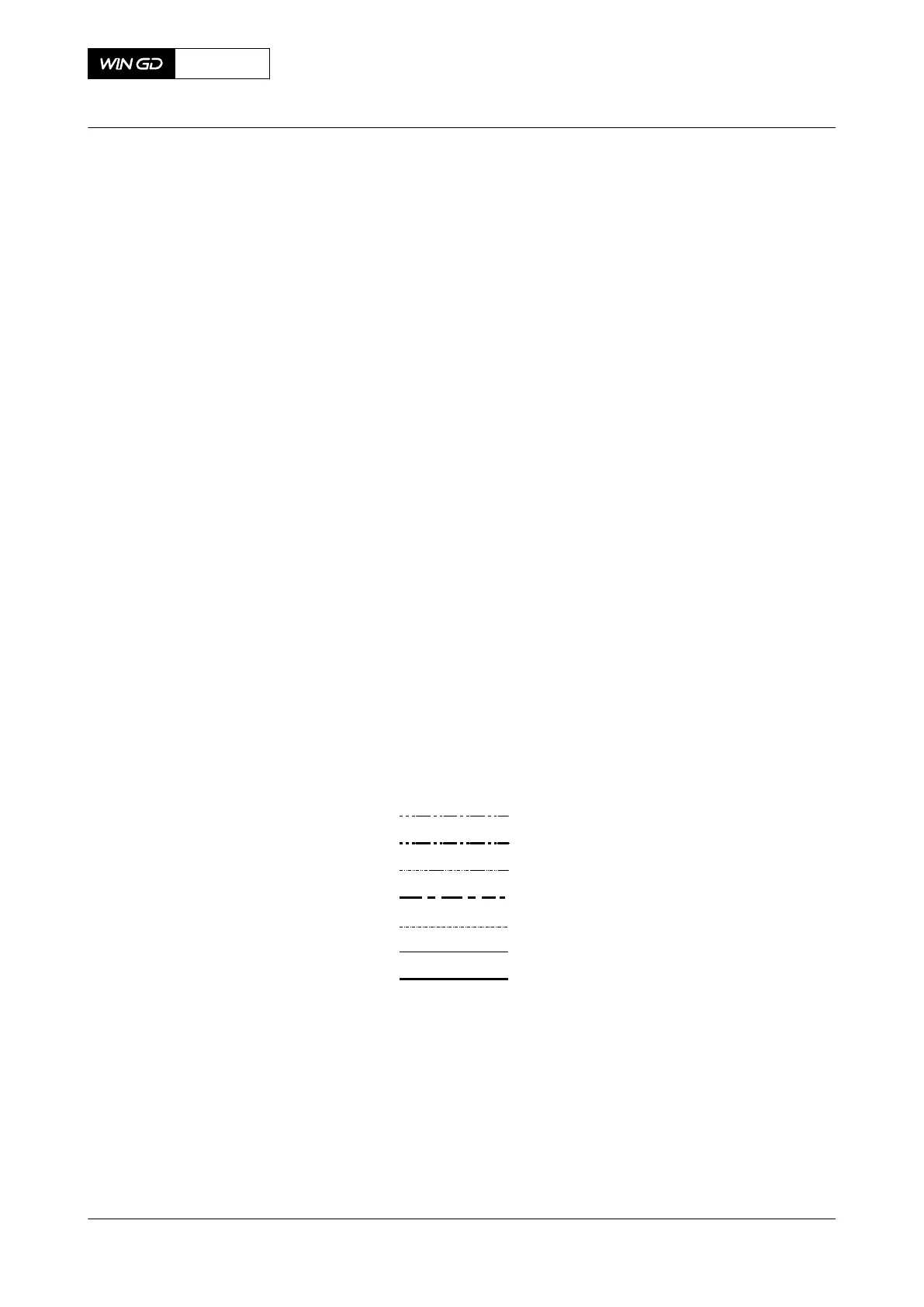
The line codes in the engine control diagram are shown in Figure 13-1.
Fig 13-1 Line codes
001
002
003
004
005
006
007
00208
Legend
001 Low pressure oil circuits 005 Heating
002 High pressure oil circuits 006 Control air circuits
003 Low pressure fuel circuits 007 Starting air circuits
004 High pressure fuel circuits
X72-B
AA00-0000-00AAA-043I-A
Operation Manual Schematic diagrams - general
Winterthur Gas & Diesel Ltd.
- 522 - Issue 003 2021-12