ENGINE
L3301, L3901, L4701, WSM
1-M13
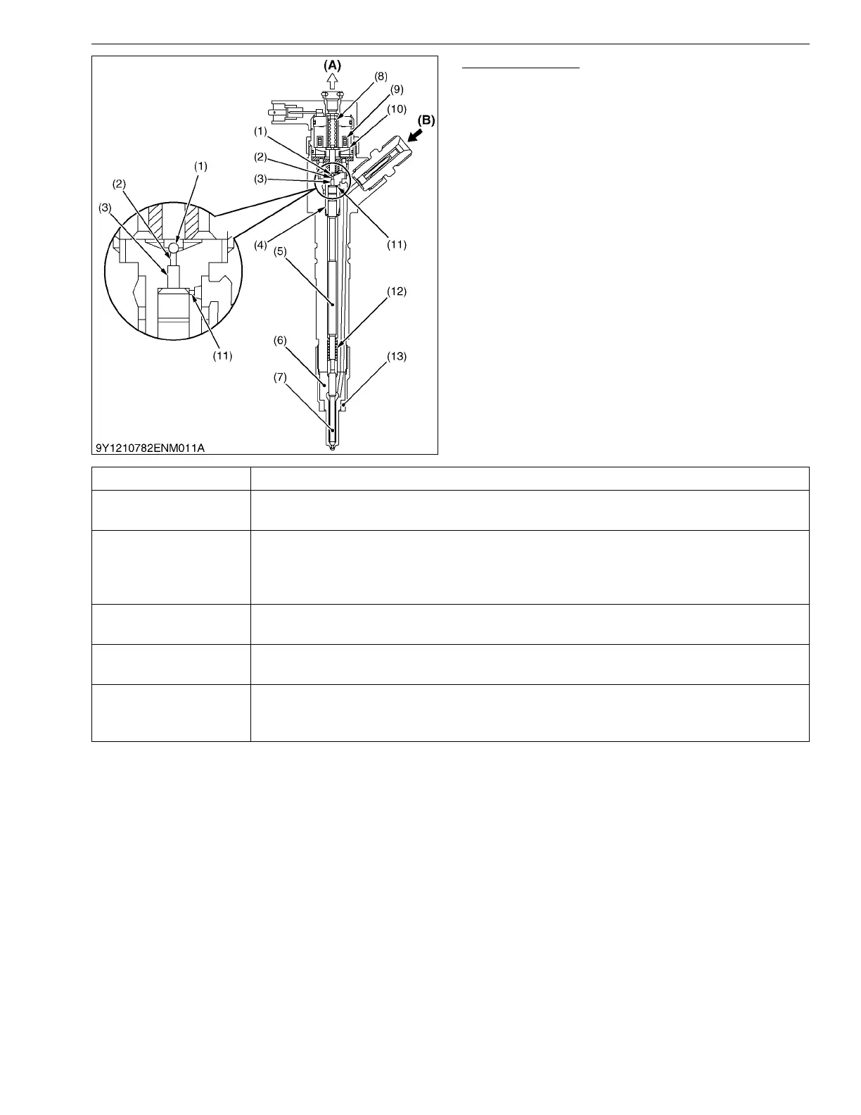
Injector Structure
Injectors consist of nozzle components (nozzle body
(6), needle valve (7), nozzle spring (12), nozzle nut (13))
and control components (control chamber (3), solenoid
(9), valve spring (8), TWV (Two Way Valve) (10), valve
ball (1), valve body (4), command piston (5), suction
orifice (11), discharge orifice (2).
9Y1211012ENM0019US0
(1) Valve Ball
(2) Discharge Orifice
(3) Control Chamber
(4) Valve Body
(5) Command Piston
(6) Nozzle Body
(7) Needle Valve
(8) Valve Spring
(9) Solenoid
(10) TWV (Two Way Valve)
(11) Suction Orifice
(12) Nozzle Spring
(13) Nozzle Nut
(A) To Fuel Tank
(B) From Rail
Part Function
Two way
electromagnetic valve
Electromagnetic valve that is operated through turning current to a solenoid ON and
OFF controlling flowing in and flowing out of fuel from the rail to the control chamber.
Suction, discharge
orifice
This sets the raise and lower speed of the needle valve through constricting discharge
and suctioning of fuel into the control chamber. Also, sets a slight delay between
operation of the two way electromagnetic valve and operation of the needle valve
enabling reliable injection of very low amounts.
Valve piston
Raises and lowers a nozzle needle through changing pressure in the control chamber
provided on top of the piston.
Nozzle spring
Along with control chamber pressure causes the needle valve to be in close contact with
the nozzle body preventing leaking of high pressure fuel from the rail.
Nozzle
Part that performs fuel injection. The needle valve is raised and lowered based on
change to pressure in the control chamber, opens and closes the fuel injection port, and
while the valve is open, atomizes and injects fuel from the rail.