ELECTRICAL SYSTEM
L3301, L3901, L4701, WSM
9-S24
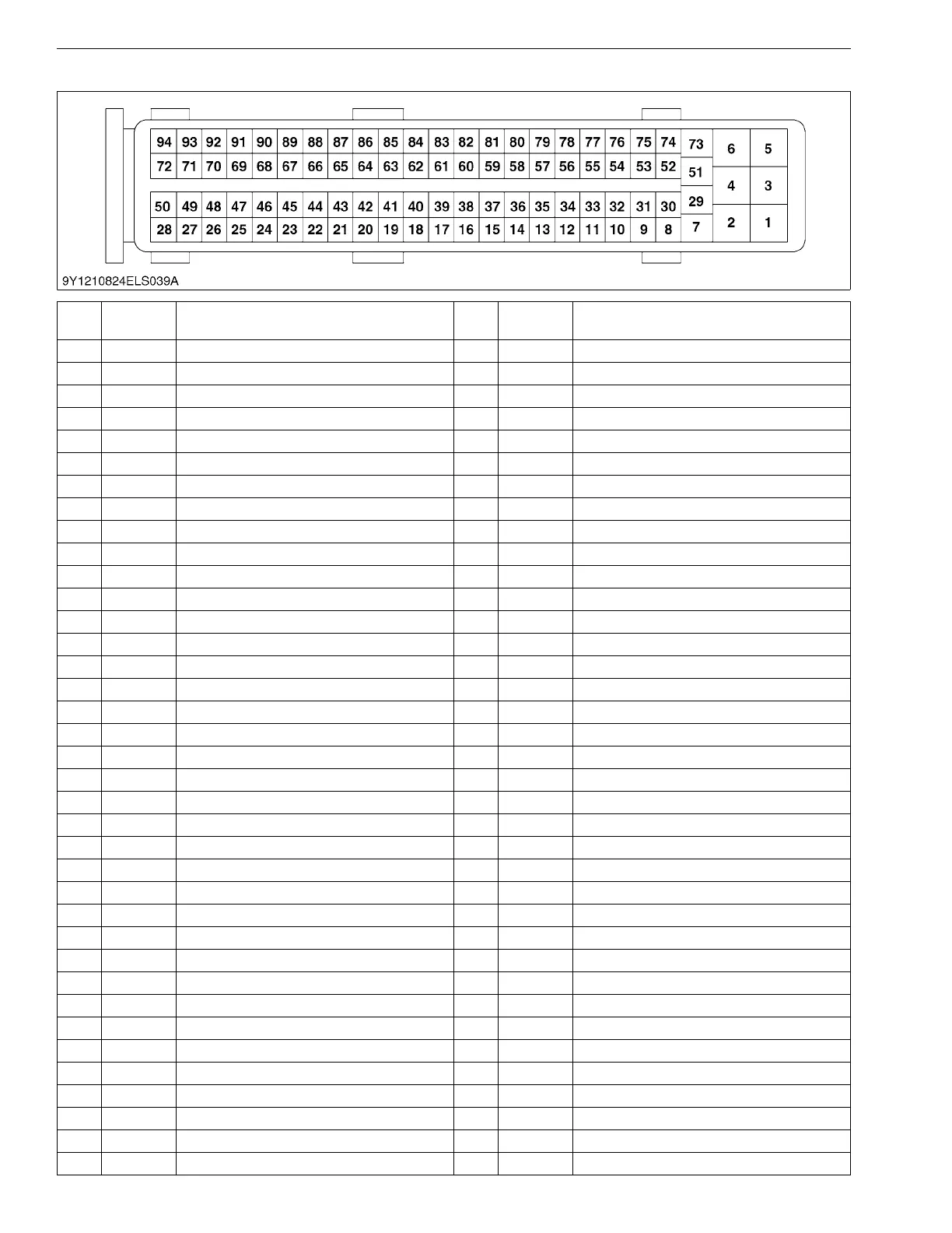
(1) Checking Electric Control Unit Connector
No.
Color of
wiring
Terminal Name No.
Color of
wiring
Terminal Name
1 BGND48 ––
2 BGND49 ––
3 R Injector #1 and #4 (+) 50 R/W Engine ECU Main Relay (Coil Side)
4 R/G Engine ECU Main Relay (Switch Side) 51 W/R Injector #2 (−)
5 R/Y Injector #2 and #3 (+) 52 ––
6 R/B Engine ECU Main Relay (Switch Side) 53 B Air Flow Sensor (−)
7 W/B Injector #4 (−) 54 Y/L Rail Pressure Sensor (Signal)
8 B Crankshaft Position Sensor (−) 55 W/B Exhaust Gas Temperature Sensor T2 (−)
9 ––56 ––
10 ––57 Y Exhaust Gas Temperature Sensor T1
11 B/Y Coolant Temperature Sensor (−) 58 ––
12 ––59 GR Exhaust Gas Temperature Sensor T0
13 B/W DPF Differential Pressure Sensor (+) 60 ––
14 ––61 W/V Air Flow Sensor (Signal)
15 ––62 RCAN2 (H)
16 ––63 BCAN2 (L)
17 ––64 ––
18 R Intake Throttle Valve Position Sensor (+) 65 W/R CAN1 (L)
19 ––66 BR CAN1 (H)
20 S/B OPC Signal 67 ––
21 ––
68 ––
22 ––69 ––
23 ––70 B/BR
Glow Rela
y (Coil Side)
24 ––71 R/B Ignition Switch
25 ––72 ––
26 ––73 W/L Injector #1 (−)
27 ––74 ––
28 ––75 W Crankshaft Position Sensor (Signal)
29 W Injector #3 (−) 76 G/B Rail Pressure Sensor (−)
30 ––77 B/L Exhaust Gas Temperature Sensor T2
31 ––78 ––
32 R/GR Rail Pressure Sensor (+) 79 P Exhaust Gas Temperature Sensor T1 (−)
33 W/G Coolant Temperature Sensor (Signal) 80 ––
34 ––81 W/R Exhaust Gas Temperature Sensor T0 (−)
35 ––82 W Intake Throttle Valve Position Sensor (−)
36 Y/B DPF Differential Pressure Sensor (−) 83 ––
37 B/P Intake Throttle Valve Position Sensor (Signal) 84 R/L Intake Throttle Valve Motor (DC Motor +)