HYDRAULIC SYSTEM
L3301, L3901, L4701, WSM
8-M16
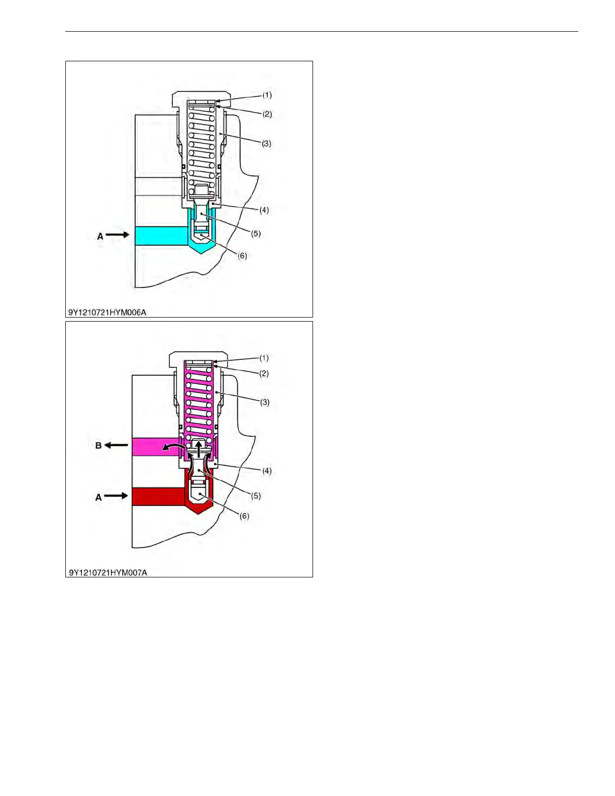
[3] RELIEF VALVE
The 3-point hydraulic circuit has a relief valve to
restrict the maximum pressure in its circuit.
This is a guide piston relief valve with damper, a
direct acting relief valve suitable for relatively high
pressure and capacity, and constructed so as to prevent
chattering and other unstableness associated with direct
acting relief valves. As shown in the figure, the poppet
(5) has a guide, and there is a valve chamber called a
damping chamber (6) in the base of this guide piston.
The valve inlet is connected to this chamber through
the clearance between the guide surface and the seat so
that the chamber provides a damping effect, controlling
valve vibration.
When the pressure in the circuit rises, the pressure
in the damping chamber also rises, and when it exceeds
the relief pressure setting the spring is compressed,
making a clearance between the poppet and the seat.
The hydraulic oil can escape to the transmission
case through this clearance, controlling the pressure
rise.
9Y1211012HYM0021US0
(1) Washer
(2) Shim
(3) Plug
(4) Seat
(5) Poppet
(6) Damping Chamber
A: From Pump
B: To Transmission Case