CLUTCH
L3301, L3901, L4701, WSM
2-S25
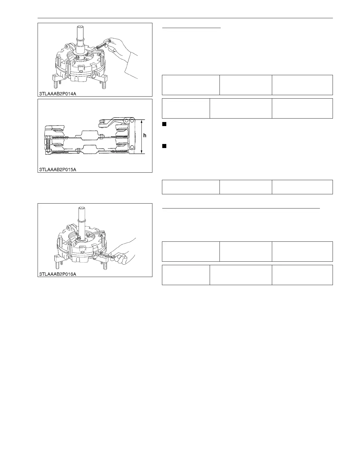
Release Lever Height
1. Mount the dual stage clutch exclusive tool (Code No.
07916-90052).
2. Measure the clearance between gauge ring and the top of
adjusting screw with a feeler gauge.
3. If the clearance is not within the factory specifications, adjust
with the adjusting screws.
• Be sure to adjust the mutual difference of release lever to
within the factory specifications.
• Apply adhesive (Cemdine No. 110 by Cemdine Industry Co.,
Ltd. or equivalent) to the adjusting screws, replace lever
and lock nuts.
(Reference)
9Y1211012CLS0025US0
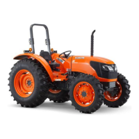
Clearance between Pressure Plate 2 and Adjusting Screw
1. Measure the clearance between pressure plate 2 and the top of
adjusting screw with a feeler gauge.
2. If the clearance is not within the factory specifications, rotate
adjusting screw to adjust.
9Y1211012CLS0026US0
Clearance between
gauge ring and the top of
adjusting screw
Factory specification
0 to 0.7 mm
0 to 0.003 in.
Tightening torque Adjusting screw lock nut
16 to 21 N·m
1.6 to 2.2 kgf·m
12 to 15 lbf·ft
Release lever height h Reference value
97.8 to 99.2 mm
3.85 to 3.90 in.
Clearance between
pressure plate 2 and
adjusting screw
Factory specification
0.90 to 1.0 mm
0.036 to 0.039 in.
Tightening torque
Pressure plate 2 height
adjusting screw lock nut
16 to 21 N·m
1.6 to 2.2 kgf·m
12 to 15 lbf·ft



 To Next Page