TRANSMISSION
L3301, L3901, L4701, WSM
3-M14
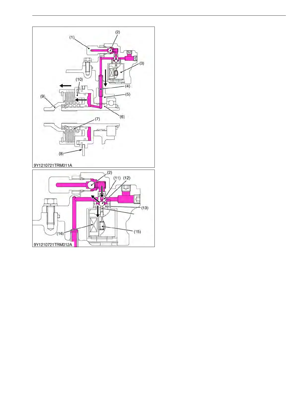
PTO Clutch Control Switch "ON" Position
When the PTO control switch is set at "ON" position
the coil (16) of the solenoid valve (3) is excited.
The rod (14) is pulled in to the solenoid valve (3) by
the excited coil (16).
The ball (9) is pushed to the seat (13) by the
pressured oil from pump port.
The pressured oil flows through the oil passage
between the ball (2) and the plunger (11) to the PTO
clutch pack.
The pressured oil in the PTO clutch pack pushes the
piston (10).
As a result, PTO clutch disks and clutch plates are
attached and the PTO clutch engages.
The power from the engine is transmitted through
PTO clutch to the rear PTO shaft.
The spring (15) pushes the rod and the ball (12) is
pushed to the plunger (11).
Since oil passage between the ball (12) and the
plunger (11) is closed, oil from the pump port is blocked
at the PTO clutch solenoid valve (3).
9Y1211012TRM0015US0
(1) Joint
(2) Ball
(3) PTO Clutch Solenoid Valve
(4) Hydraulic Pipe
(5) Mid Case
(6) I-PTO Clutch
(7) Return Spring
(8) Brake Disk
(9) Clutch Hub
(10) Piston
(11) Plunger
(12) Ball
(13) Seat
(14) Rod
(15) Spring
(16) Coil
 Loading...