TRANSMISSION
L3301, L3901, L4701, WSM
3-M36
[B] L4701
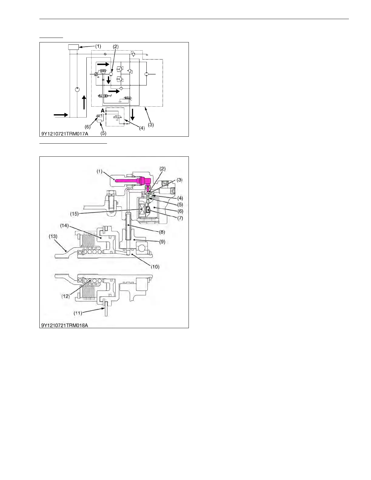
Oil Flow
The pressured oil from the charge pump (2) located
in the HST assembly (3) flows into the PTO clutch valve
(4).
When the PTO clutch control switch is at the "ON"
position, PTO clutch solenoid valve is opened and the oil
flows through the PTO clutch pack (6) to the accumulator
(5) and the PTO clutch pack (6) to engage it.
9Y1211012TRM0040US0
Function of PTO Clutch
PTO Clutch Control Switch "OFF" Position
When the PTO control switch is set at "OFF"
position, the coil is not a magnetic.
The spring pushes the rod (5) and the ball (3) is
pushed the plunger (2).
Since oil passage between the ball (3) and the
plunger (2) is closed, oil from the pump port is blocked at
the PTO clutch solenoid valve (6).
Since the pressured oil is not supplied to the PTO
clutch, the PTO clutch is not engaged.
In this condition, the return spring (12) pushes the
brake disk (11), and PTO clutch assembly does not
rotate.
9Y1211012TRM0041US0
(1) Power Steering Controller
and Cylinders
(2) Charge Pump
(3) HST Assembly
(4) PTO Valve
(5) Accumulator
(6) PTO Clutch Pack
A: PTO Clutch Operating
Pressure Check Port
(1) Joint
(2) Plunger
(3) Ball
(4) Seat
(5) Rod
(6) PTO Clutch Solenoid Valve
(7) Spring
(8) Hydraulic Pipe
(9) Mid Case
(10) I-PTO Clutch
(11) Brake Disk
(12) Return Spring
(13) Clutch Hub
(14) Piston
(15) Coil