TRANSMISSION
L3301, L3901, L4701, WSM
3-S91
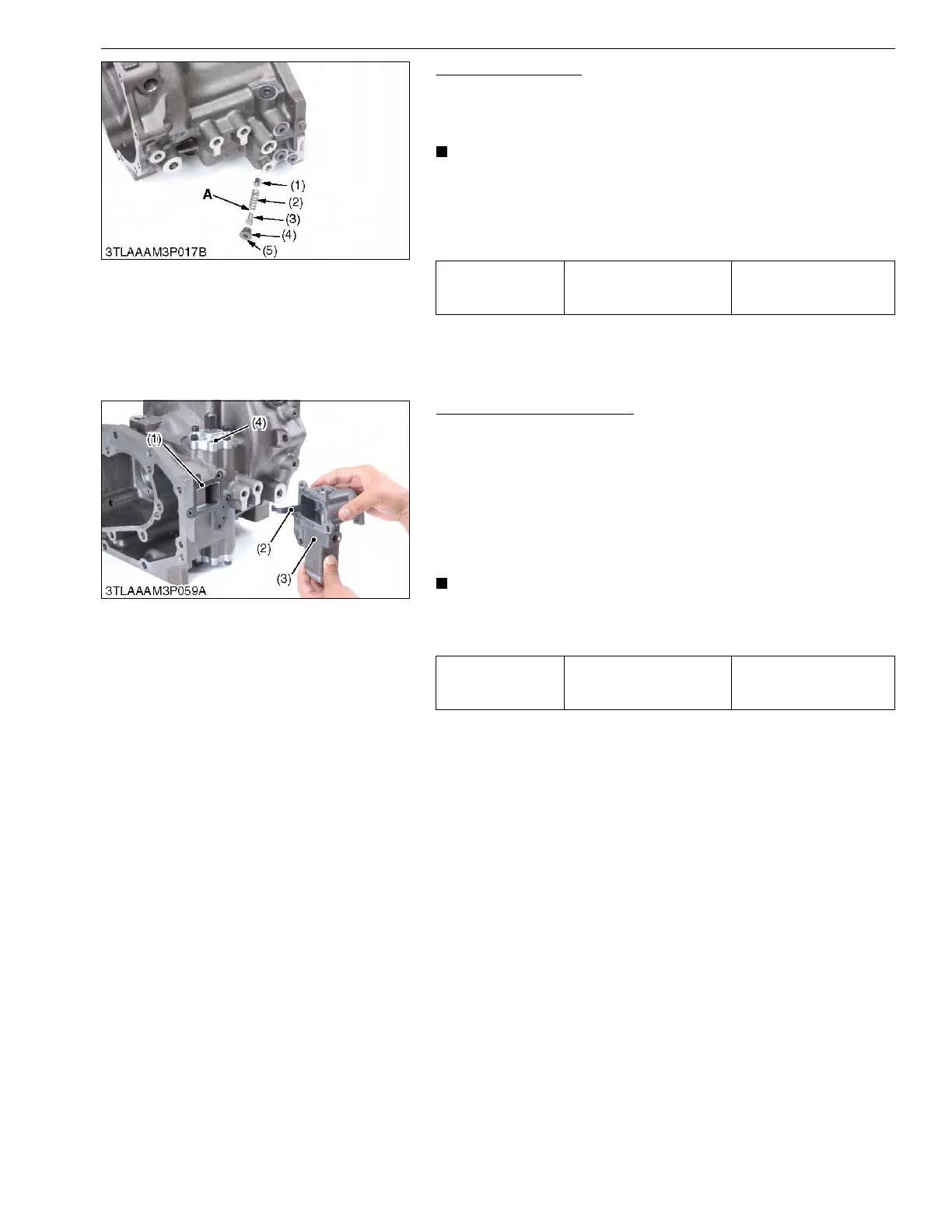
Charge Relief Valve
1. Remove the hex. head plug (5).
2. Remove the spring guide (3), the shim (if installed), the spring
(2) and the valve poppet (1).
• Install the valve component, noting the number of the
shims in the charge relief valve.
• Be careful not to damage O-ring.
• When replacing the charge relief valve, check and adjust
the charge relief valve setting pressure. (See page 3-S22.)
9Y1211012TRS0119US0
Servo Regulator Assembly
1. Remove the regulator mounting hex. head screws.
2. Remove the servo regulator assembly (3) from the HST housing
case.
(When reassembling)
• Place a new gasket on the HST housing case.
• Align the feedback lever (2) of the servo regulator and the
groove of the servo piston securely. And install the servo
regulator assembly (3) to the HST housing case.
• Since the servo regulator assembly has been factory
adjusted, do not disassemble the servo regulator
assembly.
9Y1211012TRS0120US0
Tightening torque
Charge relief valve hex.
head plug (G3/8)
49 to 59 N·m
5.0 to 6.0 kgf·m
36.2 to 43.4 lbf·ft
(1) Poppet
(2) Spring
(3) Spring Guide
(4) O-ring
(5) Plug (GPF 3/8)
A: Shim (If Shim is Installed)
Tightening torque
Servo regulator assembly
mounting hex. head screw
(M8)
29 to 34 N·m
3.0 to 3.5 kgf·m
21.7 to 25.3 lbf·ft
(1) Gasket
(2) Feedback Lever
(3) Servo Regulator Assembly
(4) Servo Piston
 Loading...