FRONT AXLE
L3301, L3901, L4701, WSM
6-S16
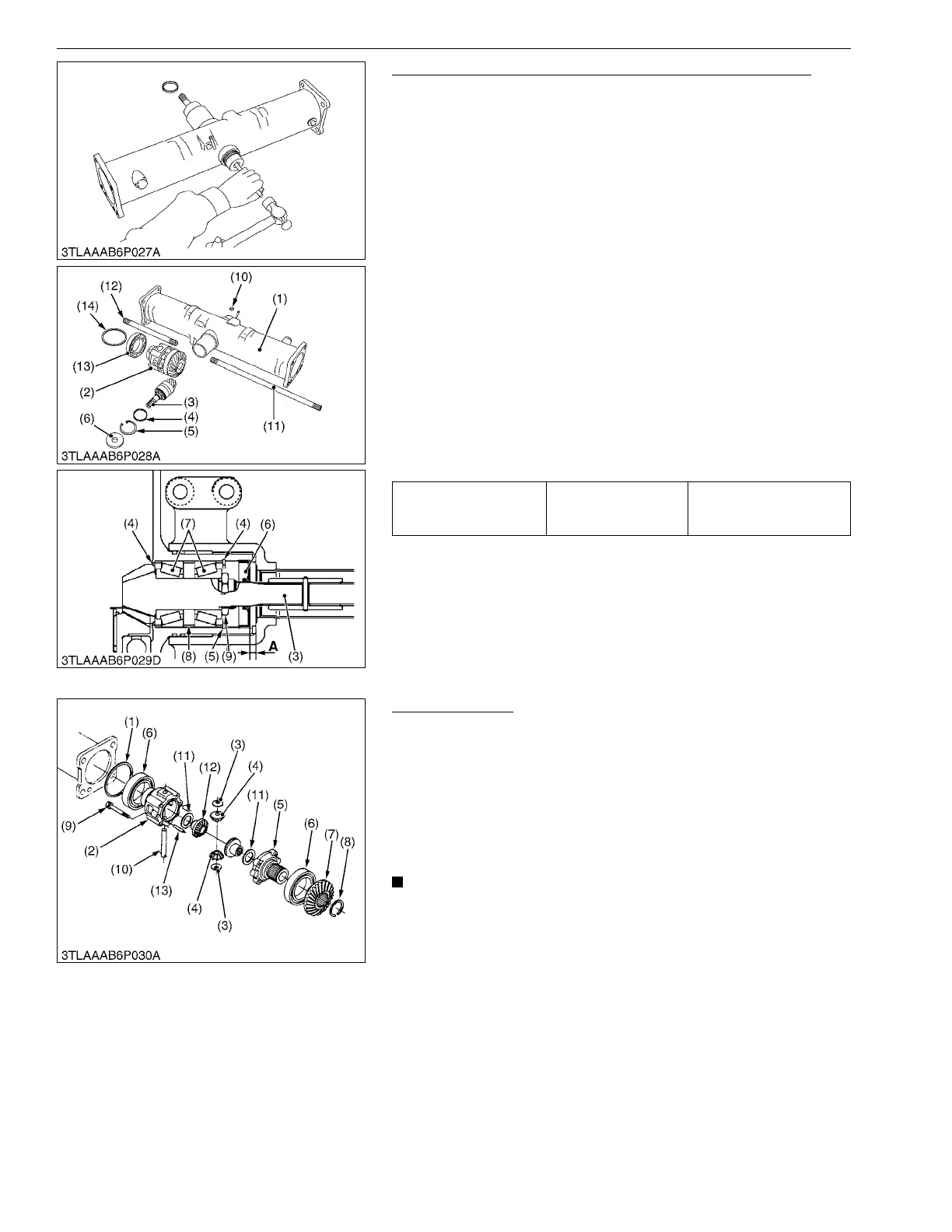
Spiral Bevel Pinion Shaft and Differential Gear Assembly
1. Remove the differential yoke shaft (11), (12) both sides.
2. Remove the oil seal (6) and internal snap ring (5).
3. Remove the plug (10), and then tap out the spiral bevel pinion
shaft (3) by the brass rod and hammer.
4. Remove the differential gear assembly (2), ball bearing (13) and
shim (14) from right side of front axle case (1).
5. Remove the stake of lock nut (9), and then remove the lock nut
(9).
6. Remove the taper roller bearings (7).
(When reassembling)
• Replace the lock nut (9), oil seal (6) and plug (10) with new
ones.
• Apply grease to the oil seal (6).
• Install the same shims and collars before they are removed.
• Install the taper roller bearings correctly, noting their direction,
and apply gear oil to them.
• When press-fitting a oil seal (6), observe the dimension "A"
described in the figure.
• Stake the lock nut (9) firmly.
• Tighten up the lock nut (9) until the turning force of the spiral
bevel pinion shaft reaches the factory specifications.
9Y1211012FAS0019US0
Differential Gear
1. Remove the differential case cover mounting screws (9) and
then remove the differential case cover (5), ball bearing (6) and
spiral bevel gear (7) as a unit.
2. Remove the external snap ring (8), and then remove the ball
bearing (6) and spiral bevel gear (7) as a unit with a puller.
3. Remove the straight pin (13).
4. Pull out the pinion shaft (10) and remove the differential pinions
(4) and differential side gears (12).
• Arrange the parts to know their original position.
(When reassembling)
• Apply molybdenum disulfide (Three Bond 1901 or equivalent) to
the inner circumferential surface of the differential side gears
(12) and differential pinions (4).
• Install the pinion shaft (10) so that the hole on it may align with
the hole on differential case (2), and install the straight pin (13).
9Y1211012FAS0020US0
Turning torque of spiral
bevel pinion shaft
Factory specification
0.98 to 1.1 N·m
0.10 to 0.12 kgf·m
0.73 to 0.86 lbf·ft
(1) Front Axle Case
(2) Differential Gear Assembly
(3) Spiral Bevel Pinion Shaft
(4) Adjusting Collar
(5) Internal Snap Ring
(6) Oil Seal
(7) Taper Roller Bearing
(8) Collar
(9) Lock Nut
(10) Plug
(11) Differential Yoke Shaft R.H.
(12) Differential Yoke Shaft L.H.
(13) Ball Bearing
(14) Shim
A: 1 mm (0.04 in.)
(1) Shim
(2) Differential Case
(3) Thrust Collar
(4) Differential Pinion
(5) Differential Case Cover
(6) Ball Bearing
(7) Spiral Bevel Gear
(8) External Snap Ring
(9) Screws
(10) Pinion Shaft
(11) Shim
(12) Differential Side Gear
(13) Straight Pin
 Loading...