HYDRAULIC SYSTEM
L3301, L3901, L4701, WSM
8-S21
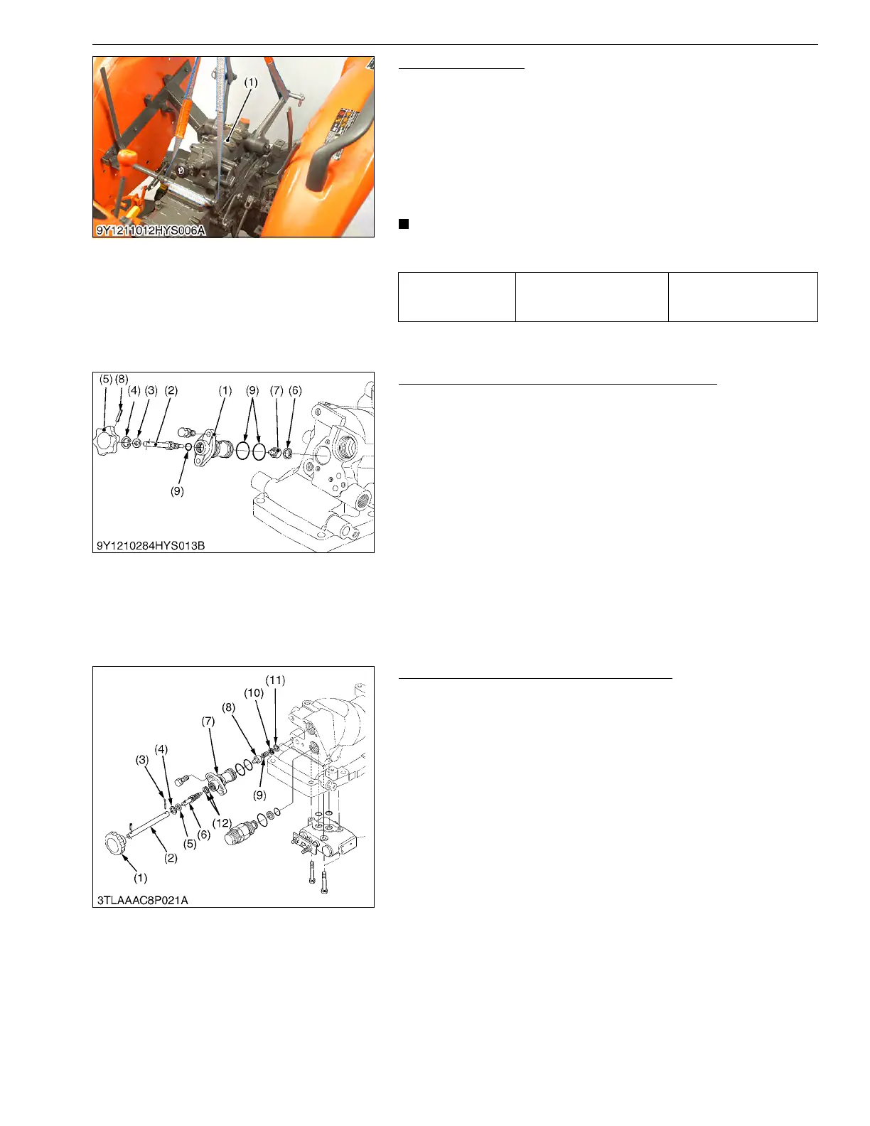
Hydraulic Cylinder
1. Loosen and remove the hydraulic cylinder assembly mounting
bolts and nuts.
2. Support the hydraulic cylinder assembly with nylon strap and
crane and remove it.
(When reassembling)
Apply liquid gasket (Three Bond 1206C or equivalent) to joint
face of the hydraulic cylinder assembly and transmission case after
eliminate the water, oil and stuck liquid gasket (L4701 only).
• Reassemble the hydraulic cylinder assembly to the tractor,
be sure to adjust the feedback rod (See page 8-S15).
9Y1211012HYS0013US0
Lowering Speed Adjusting Valve (L3301/L3901)
1. Remove the lowering speed adjusting valve from hydraulic
cylinder block.
2. Tap out the spring pin (8), and remove the grip (5).
3. Remove the internal cir-clip (4), and remove the hydraulic
adjusting shaft (2).
4. Remove the internal cir-clip (6) and draw out the adjusting collar
(7).
(When reassembling)
• Install the hydraulic adjusting shaft (2) and valve body (1),
noting O-ring (9).
9Y1211012HYS0014US0
Lowering Speed Adjusting Valve (L4701)
1. Remove the lowering speed adjusting valve assembly from
hydraulic cylinder block.
2. Remove the internal snap ring (4), and remove the hydraulic
adjusting shaft (6).
3. Remove the internal snap ring (11), and draw out the spring (9)
and adjusting collar (8).
(When reassembling)
• Install the hydraulic adjusting shaft (6) to valve body (7), noting
two O-rings (12).
9Y1211012HYS0015US0
Tightening torque
Hydraulic cylinder
assembly mounting bolt
78 to 90 N·m
7.9 to 9.2 kgf·m
58 to 66 lbf·ft
(1) Hydraulic Cylinder Assembly
(1) Valve Body
(2) Hydraulic Adjusting Shaft
(3) Washer
(4) Internal Cir-clip
(5) Grip
(6) Internal Cir-clip
(7) Adjusting Collar
(8) Spring Pin
(9) O-ring
(1) Grip
(2) Extension Shaft
(3) Cotter Pin
(4) Internal Snap Ring
(5) Washer
(6) Hydraulic Adjusting Shaft
(7) Valve Body
(8) Adjusting Collar
(9) Spring
(10) Washer
(11) Internal Snap Ring
(12) O-ring



 To Next Page